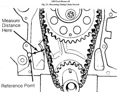
Timing chains will stretch during operation. Limits are placed upon amount of stretch before replacement is required. Timing chain stretch will alter ignition timing and valve timing. To check timing chain stretch, rotate crankshaft to eliminate slack from one side of timing chain. Mark reference point on cylinder block. Rotate crankshaft in opposite direction to eliminate slack from remaining side of timing chain. Force other side of chain outward and measure distance between reference point and timing chain. See Fig. 23 . Replace timing chain and gears if not within specification. Fig. 23: Measuring Timing Chain Stretch Timing chains must be installed so timing marks on camshaft gear and crankshaft gear are aligned according to manufacturer. See Fig. 24 . Fig. 24: Typical Gear Timing Mark Alignment

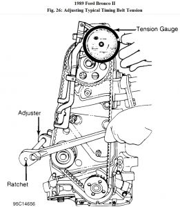
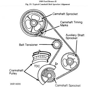
Cogged tooth belts are commonly used on overhead cam engines. Inspect belt teeth for rounded corners or cracking. Replace belt if it is cracked, damaged, missing teeth or oil soaked. Used timing belt must be installed in original direction of rotation. Inspect all sprocket teeth for wear. Replace all worn sprockets. Sprockets are marked for timing purposes. Engine is positioned so that crankshaft sprocket mark will be upward. Camshaft sprocket is aligned with reference mark on cylinder head or timing belt cover and then timing belt can be installed. See Fig. 25 . Fig. 25: Typical Camshaft Belt Sprocket Alignment TENSION ADJUSTMENT If guide rails are used with spring loaded tensioners, ensure at least half of original rail thickness remains. Spring loaded tensioner should be inspected for damage. Ensure all timing marks are aligned. Adjust belt tension using manufacturer's recommendations. Belt tension may require checking using tension gauge. See Fig. 26 . Fig. 26: Adjusting Typical Timing Belt Tension TIMING GEARS * PLEASE READ THIS FIRST *
Examples used in this article are general in nature and do not necessarily relate to a specific engine or system. Illustrations and procedures have been chosen to guide mechanic through engine overhaul process. Descriptions of processes of cleaning, inspection, assembly and machine shop practice are included. Always refer to appropriate engine overhaul article, if available, in the ENGINES section for complete overhaul procedures and specifications for the vehicle being repaired. TIMING GEAR BACKLASH & RUNOUT On engines where camshaft gear operates directly on crankshaft gear, gear backlash and runout must be checked. To check backlash, install dial indicator with tip resting on tooth of camshaft gear. Rotate camshaft gear as far as possible. Adjust indicator to zero. Rotate camshaft gear in opposite direction as far as possible and note reading. To determine timing gear runout, mount dial indicator with tip resting on face edge of camshaft gear. Adjust indicator to zero. Rotate camshaft gear 360 degrees and note reading. If backlash or runout exceeds specification, replace camshaft and/or crankshaft gear.
TIMING CHAIN & SPROCKETS Removal 1. Position No. 1 cylinder on TDC of compression stroke. Ensure damper timing marks align properly. Remove engine front cover. See REMOVAL under ENGINE FRONT COVER in this article. Note timing mark alignment for camshaft and crankshaft sprockets for installation reference. 2. Remove timing chain tensioner. Check timing chain deflection. See TIMING CHAIN DEFLECTION under TIMING CHAIN & SPROCKETS in this article. Remove camshaft sprocket retaining bolt. Remove camshaft sprocket and timing chain. Using a gear puller, remove crankshaft sprocket. Timing Chain Deflection 1. Rotate crankshaft counterclockwise just enough to take up chain slack on left side (opposite side of tensioner). Mark a reference point on block, mid-point between sprockets. 2. Measure and record distance from reference point to chain. Rotate crankshaft clockwise just enough to take up chain slack on right side (tensioner side). Pull out left side of chain and measure distance from chain to reference point. 3. The difference between both measurements is the deflection. Replace timing chain and sprockets as necessary. If wear on tensioner face exceeds .06" (1.5 mm), replace tensioner. Return sprockets to TDC. Installation 1. Fill keyway chamfer with Threadlock or sealer. Align crankshaft sprocket keyway with key on crankshaft. Install crankshaft sprocket with an installer. See Fig. 6 . Ensure timing mark on crankshaft sprocket is aligned as noted at removal. Place timing chain on camshaft sprocket. 2. Align camshaft sprocket keyway with key on camshaft and slide sprocket and chain onto camshaft. Ensure timing marks align as noted at removal. Install and tighten camshaft retaining bolt. Check camshaft end play. See CAMSHAFT END PLAY in this article. To complete installation, reverse removal procedure. NOTE: Timing chain deflection specifications are not available from manufacturer.
With the gears and marks aligned, the distributor should be firing #1 cylinder. Marks on the crank and cam should align as seen in the pictures.
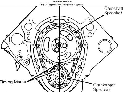
The bottom gear is actually the crankshaft, the picture shows it as a second camshaft...
Jul 3, 2010 at 7:15 AM
