ENGINE SENSORS & SWITCHES SENSORS & SWITCHES Camshaft Position Sensor (Synchronization Signal Generator) 1. Use an analog voltmeter. DO NOT remove distributor connector from distributor. Insert voltmeter leads into backside of distributor wiring harness connector to make contact with terminals. Ensure that connector is not damaged when inserting test probes. 2. Insert positive voltmeter lead into synchronization signal output Tan/Yellow wire on Cherokee and Comanche (Gray/Black wire on Wrangler) at distributor wiring harness connector. 3. Insert negative voltmeter lead into ground Black/Blue wire (Brown/Red wire on Wrangler) at distributor wiring harness connector. Set voltmeter to 15-volt DC scale. 4. With distributor cap removed, manually rotate engine until pulse ring enters sync signal generator. Turn ignition switch to ON position. With pulse positioned in the sync generator, reading should be about 5 volts. 5. If no voltage is indicated, check voltmeter leads for good connections If connections are okay and there is still no voltage, check for voltage at Orange supply wire on Cherokee and Comanche (White/Black wire on Wrangler). 6. If no voltage is indicated at supply wire, remove engine controller and check voltage at pin No. 7. Engine controller is located on left side of engine compartment. If there is no voltage at engine controller, see appropriate synchronization sensor/circuit tests in the appropriate TESTS W/CODES article. 7. If voltage is indicated at engine controller pin No. 7, but not at supply wire, check continuity of supply wire between the distributor connector and the engine controller. If no continuity exists, repair wiring harness as necessary. 8. If supply wire is okay, check continuity between sync signal output wire at the distributor connector and pin No. 44 at engine controller. If no continuity exists, repair wiring harness as necessary. 9. If sync signal output wire is okay, check continuity between ground circuit wire at the distributor connector and ground. If no continuity exists, repair wiring harness as necessary. If ground wire is okay, go to next step. 10. While observing voltmeter, crank engine. Voltmeter needle should fluctuate from 0-5 volts while the engine is cranking. This verifies that stator in distributor is operating properly and that a sync (pulse) signal is being generated. If voltmeter does not fluctuate, replace synch sensor stator. Coolant Temperature Sensor 1. Disconnect coolant temperature sensor. Using a DVOM, check the sensor resistance. Resistance should be as specified in the COOLANT TEMP SENSOR & MANIFOLD AIR TEMP SENSOR RESISTANCE table. Replace sensor if necessary. 2. Check continuity between engine controller wiring harness terminal No. 2 and sensor connector terminal. Also check continuity between engine controller wiring harness terminal No. 4 and sensor connector terminal. Repair wiring if an open circuit is indicated. Crankshaft Position Sensor 1. Disconnect crankshaft position sensor. On Cherokee and Comanche, connect ohmmeter across sensor terminal "A" (Orange/Dark Blue wire) and terminal "B" (Black/Light Blue wire). On Wrangler, connect ohmmeter across sensor terminal "A" (Brown/Red wire) and terminal "B" (Red/Green wire). 2. Ohmmeter should read 125-275 ohms with engine hot. Replace sensor if reading is not as specified. Also see appropriate crankshaft position sensor tests in TESTS W/CODES article in this section. Manifold Absolute Pressure (MAP) Sensor 1. Inspect MAP sensor vacuum hose connections at throttle body and sensor. Replace or repair vacuum hose if necessary. 2. Turn ignition on, engine off. Using DVOM, check MAP sensor output voltage. On Cherokee and Comanche, connect DVOM to MAP sensor terminal "B" (Dark Green/Red wire). On Wrangler, connect DVOM to MAP sensor terminal "B" (Red/White wire). 3. Output voltage should be 4-5 volts. Voltage should drop to 1.5-2.1 volts with a hot engine operating in Neutral and at idle speed. Also check for output voltage at engine controller wiring harness terminal No. 1. If voltage is not as specified in step 2), repair wiring harness if necessary. 4. With ignition on, check MAP sensor supply voltage at sensor connector terminal "C" (Violet wire on Cherokee and Comanche or Brown/Yellow wire on Wrangler). Supply voltage should be 4.5-5.5 volts. Also check for supply voltage at engine controller wiring harness terminal No. 6. If supply voltage is not as specified, repair wiring harness if necessary.
Check continuity of MAP sensor ground circuit at sensor connector terminal "A" (Black/Light Blue wire on Cherokee and Comanche or Brown/Red wire on Wrangler) and engine controller wiring harness terminal No. 4. Repair wiring harness if necessary.
Check continuity of MAP sensor ground circuit at engine controller wiring harness terminal No. 4 and engine controller wiring harness terminal No. 11. If ohmmeter indicates an open circuit, go to next step. If ground connection is okay, replace the engine controller.
Check for defective sensor ground connection. Connection is located on right side of engine block, at oil dipstick tube mounting block. Repair connection as necessary. Manifold Air Temperature (MAT) Sensor
Disconnect coolant temperature sensor. Using a DVOM, check the sensor resistance. Resistance should be as specified in the COOLANT TEMP SENSOR & MANIFOLD AIR TEMP SENSOR RESISTANCE table. If resistance is not as specified, replace sensor.
Check resistance between engine controller wiring harness terminal No. 21 and sensor connector terminal. Also check resistance between engine controller wiring harness terminal No. 4 and sensor connector terminal. Repair wiring if resistance is greater than 1 ohm. Oxygen (O2) Sensor (Heating Element)
Disconnect oxygen sensor connector. Using an ohmmeter, check sensor heating element resistance.
On Comanche and Cherokee, connect ohmmeter to Black/Tan and Dark Green/Black sensor wires. On Wrangler, connect ohmmeter to Black and Dark Green/Black sensor wires.
Heating element resistance should be 5-7 ohms. Replace oxygen sensor if ohmmeter reads infinity. Park/Neutral Switch (AW-4 Auto. Trans.)
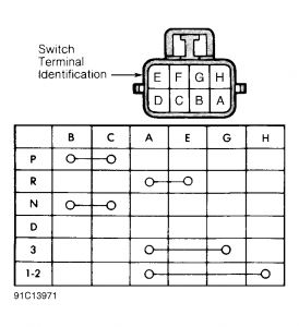
Disconnect park/neutral switch. Ensure continuity exists between terminals "B" and "C" with transmission in Park or Neutral. See Fig. 1 .
Ensure continuity exists between terminals "A" and "E" with transmission in Reverse. See Fig. 1 . Ensure continuity exists between terminals "A" and "G" with transmission in 3rd gear.
Ensure continuity exists between terminals "A" and "H" with transmission in 1st or 2nd gear. See Fig. 1 . If switch fails continuity tests, replace park/neutral switch.
1: Testing Park/Neutral Switch Continuity (AW-4 Auto. Trans.) NOTE: If terminal No. 4 has a short circuit to 12 volts, correct this condition before replacing engine controller. If necessary, perform appropriate MAP sensor tests in TESTS W/CODES article in this section.Park/Neutral Switch (32RH Auto. Trans.) 1. Disconnect park/neutral switch. Check continuity between switch center terminal and transmission case. Continuity should exist only when transmission is in Park or Neutral. 2. Shift transmission into Reverse. Check continuity between the 2 outside terminals on switch. Continuity should exist only when transmission is in Reverse. Check continuity between each outer terminal and transmission case. 3. Continuity should not exist between either terminal and case while in Reverse. If switch continuity tests are okay, check gearshift adjustment or back-up light circuit. If switch fails continuity tests, replace park/neutral switch. Throttle Position Sensor (TPS) 1. Turn ignition on. Check TPS output voltage at sensor wiring harness center terminal. At idle, output voltage should be greater than 200 millivolts. 2. Gradually open throttle plate. Output voltage should gradually increase as throttle plate is opened. At wide open throttle, output voltage must be less than 4.8 volts.
W/CODES article in this section. NOTE: Also see appropriate throttle position sensor tests in TESTS W/CODES article in this section.


Thursday, September 24th, 2020 AT 6:31 PM
(Merged)


