Thursday, April 29th, 2021 AT 1:32 PM
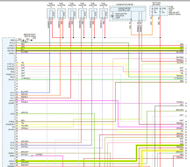
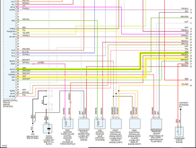
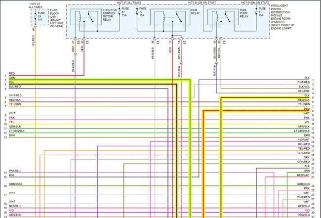
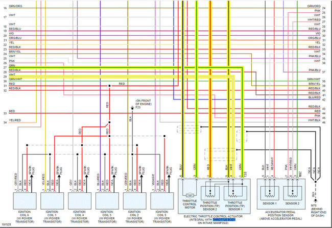
Thank you. I got this worry with a live data on the throttle moto relay shows of while the car idles. My question is, should the throttle body relay on IDPM fuse box stays on while vehicle idles, or it is normal to be off while engine is running. Secondly, when does the throttle moto relay comes on, when key is opened to acc? The car will not accelerate while on idling. Before replacing the electronic throttle body, I need to be sure I got no issues with the relay. Thanks.
