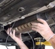
Its an automatic idle speed motor it targets the idle speed at all times and report changes to the computer
TEST DR-17A - AUTOMATIC IDLE SPEED (AIS) MOTOR CIRCUITS (DTC 25)
NOTE:For connector terminal identification, see CONNECTOR IDENTIFICATION. For appropriate wiring diagram, see WIRING DIAGRAMS.
Disconnect AIS motor connector. Turn ignition switch to ON position. Using DRB-II, actuate AIS motor. Put DRB-II in voltmeter mode. Probe Gray/Red wire in AIS motor connector. When normal, voltage will switch from less than one volt to more than 10 volts.
If voltage is less than one volt, repair short to ground in Gray/Red wire. Perform VERIFICATION PROCEDURE VER-2. If voltage is more than one volt, check if voltage is more than 10 volts. If voltage is more than 10 volts, repair short to voltage in Gray/Red wire. Perform VERIFICATION PROCEDURE VER-2. If voltage is less than 10 volts, go to next step.
Probe terminal No. 2 (Yellow/Black wire) in AIS motor connector. If voltage is less than one volt, repair short to ground in Yellow/Black wire. If voltage is more than one volt, check if voltage is more than 10 volts. If voltage is more than 10 volts, repair short to voltage in Yellow/Black wire. Perform VERIFICATION PROCEDURE VER-2. If voltage is less than 10 volts, go to next step.
Probe terminal No. 3 (Brown/White wire) in AIS motor connector. If voltage is less than one volt, repair short to ground in Brown/White wire. Perform VERIFICATION PROCEDURE VER-2. If voltage is more than one volt, go to next step.
Probe Violet/Black wire in AIS motor connector. If voltage is less than one volt, repair short to ground in Violet/Black wire. Perform VERIFICATION PROCEDURE VER-2. If voltage is more than one volt, turn ignition switch to OFF position. Reconnect AIS motor connector. Disconnect Single Board Engine Controller (SBEC) connector.
Check resistance between terminals No. 39 (Gray/Red wire) and 59 (Violet/Black wire) using an external ohmmeter. Replace defective AIS motor if resistance is less than 35 ohms. Perform VERIFICATION PROCEDURE VER-2. If resistance is more than 35 ohms, go to next step.
Check resistance between terminals No. 40 (Brown/White wire)and 60 (Yellow/Black wire). If resistance is less than 35 ohms, replace defective AIS motor. Perform VERIFICATION PROCEDURE VER-2. If resistance is more than 35 ohms, go to next step.
Check resistance between terminals No. 39 (Gray/Red wire) and 60 (Yellow/Black wire). If resistance is less than 10 ohms, Yellow/Black wire is shorted to Gray/Red wire. Repair as necessary. Perform VERIFICATION PROCEDURE VER-2. If resistance is more than 10 ohms, check if resistance is less than 75 ohms. If resistance is more than 75 ohms, go to next step. If resistance is less than 75 ohms, go to step 10.
If resistance is 75-120 ohms, Brown/White wire is shorted to Violet/Black wire. Repair wiring as necessary. Perform VERIFICATION PROCEDURE VER-2. If resistance is more than 120 ohms, replace SBEC. Perform VERIFICATION PROCEDURE VER-2.
If resistance between terminals No. 39 and 60 is less than 75 ohms in step 8), check resistance between terminals No. 59 (Violet/Black wire) and 60 (Yellow/Black wire). If resistance is less than 10 ohms, Yellow/Black wire is shorted to Violet/Black wire; if resistance is more than 10 ohms, Gray/Red wire is shorted to Brown/White wire. Repair wiring as necessary. Perform VERIFICATION PROCEDURE VER-2.
Thursday, February 5th, 2009 AT 10:26 PM


