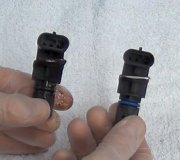
Hello. Thanks for the donation. Much appreciated
Is the PCM throwing any codes now you have battery charge and have been cranking? It should be picking up on where the fault lies? Can you check CMP sensor & wiring !
DISTRIBUTORLESS IGNITION SYSTEM (DIS)
DIS eliminates mechanical ignition components that can wear out. PCM has complete ignition control and uses a coil pack, CMP sensor and CKP sensor to control ignition timing. CMP sensor reads slots in cam timing sprocket. PCM uses this information along with information from CKP sensor to determine if fuel injectors and ignition coils are properly sequenced for correct cylinders.
Basic timing is determined by CKP sensor position and is not adjustable. One complete engine revolution may be required for PCM to determine crankshaft position during cranking.
Molded ignition coils are used. Each coil fires 2 paired spark plugs at the same time. One cylinder is on compression stroke and other cylinder is on exhaust stroke.
TEST TC-1A: NO CAM SIGNAL AT PCM
NOTE:For connector terminal identification, see CONNECTOR IDENTIFICATION. For wiring diagram, see WIRING DIAGRAMS article.
Using scan tool, erase DTCs. Attempt to start engine. If engine will not start, crank engine for at least 15 seconds. Using scan tool, read DTCs. If NO CAM SIGNAL AT PCM returned, go to next step. If NO CAM SIGNAL AT PCM did not return, got to TEST TC-1C.
Turn ignition off. On 2.5L, go to next step. On 2.0L and 2.4L, disconnect Camshaft Position (CMP) sensor connector. On 2.0L and 2.4L, CMP sensor is located on end of cylinder head. Go to step 4).
On 2.5L, disconnect 6-pin distributor connector. Camshaft Position (CMP) sensor is located inside distributor. Go to next step.
On all models, inspect connector for damaged or pushed out terminals. Repair as necessary. Perform TEST VER-2A. If connector is okay, go to next step.
Using an ohmmeter, check resistance between CMP sensor connector (harness side) ground circuit and ground. See CMP SENSOR CONNECTOR WIRE IDENTIFICATION table. If resistance is less than 5 ohms, go to next step. If resistance is 5 ohms or more, repair open ground circuit to harness splice. Perform TEST VER-2A.
Turn ignition on. Using a voltmeter, check voltage of CMP sensor connector (harness side) 8-volt supply circuit. See CMP SENSOR CONNECTOR WIRE IDENTIFICATION table.
If voltage is more than 7 volts, go to next step. If voltage is 7 volts or less, repair 8-volt supply circuit. Perform TEST VER-2A.
Turn ignition off. Connect a jumper wire to CMP sensor signal circuit. See CMP SENSOR CONNECTOR WIRE IDENTIFICATION table. Turn ignition on. Using scan tool, note CMP sensor signal state. While observing scan tool display, tap other end of jumper wire to CMP sensor ground circuit. See CMP SENSOR CONNECTOR WIRE IDENTIFICATION table.
If CMP state changes, go to TEST TC-1B. If CMP state does not change, turn ignition off. Disconnect PCM connectors. Using an ohmmeter, check resistance of CMP sensor signal circuit between CMP sensor connector (harness side) and PCM connector terminal No. 33 (sensor ground). See CMP SENSOR CONNECTOR WIRE IDENTIFICATION table and POWERTRAIN CONTROL MODULE WIRE IDENTIFICATION table. If resistance is less than 5 ohms, go to next step. If resistance is 5 ohms or more, repair open CMP sensor signal circuit. Perform TEST VER-2A.
Using an ohmmeter, check resistance between CMP sensor connector (harness side) signal circuit and sensor ground circuit. If resistance is 5 ohms or more, go to next step. If resistance is less than 5 ohms, repair signal circuit for shorting to sensor ground circuit. Perform TEST VER-2A.
Using an ohmmeter, check resistance between CMP sensor connector (harness side) signal circuit and ground. If resistance is 5 ohms or more, go to next step. If resistance is less than 5 ohms, repair signal circuit for shorting to ground. Perform TEST VER-2A.
Using an ohmmeter, check resistance between CMP sensor connector (harness side) signal circuit and 8-volt supply circuit. If resistance is 5 ohms or more, replace PCM. Perform TEST VER-2A. If resistance is less than 5 ohms, repair signal circuit for shorting to 8-volt supply circuit. Perform TEST VER-2A.
CMP SENSOR CONNECTOR WIRE IDENTIFICATION
ApplicationWire Color
CMP 8-Volt Supply Circuit
Avenger, Sebring Coupe & Talon (1) Yellow
Breeze, Cirrus, Sebring Conv, Stratus & NeonOrange
CMP Signal Circuit
Avenger, Sebring Coupe & Talon 2.0LDark Blue/Red
Avenger & Sebring Coupe 2.5L(1) Brown
Breeze, Cirrus, Sebring Conv, Stratus & Neon (1) Tan/Yellow
CMP Ground Circuit
Avenger, Sebring Coupe & Talon (1) (2) Black/Dark Green
Breeze, Cirrus, Sebring Conv, Stratus & Neon (1) (2) Black/Light Blue
(1)On 2.5L V6, camshaft position sensor wire is located at distributor connector.
(2)On 2.5L V6, ensure sensor ground is tested, not distributor ground.
POWERTRAIN CONTROL MODULE WIRE IDENTIFICATION
ApplicationWire Color
PCM Terminal No. 33 (CMP Sensor Signal Circuit)
F24S & FJ22 Bodies
2.0LDark Blue/Red
2.5LBrown
JA, JX & PL Bodies
SPONSORED LINKS
Tuesday, February 10th, 2009 AT 6:16 PM


