Is your check engine light on? If yes turn the key from off to on three times, on the fourth one leave it in the on position, count the flashes...22 would flash as 2 blinks, then a short puase, then 2 more blinks...if several codes are stored, the pause is longer between codes, code 55 will be the last code...do this and post all codes found...
I suspect a bad crank sensor, without a signal from the crank sensor, you will have no spark.
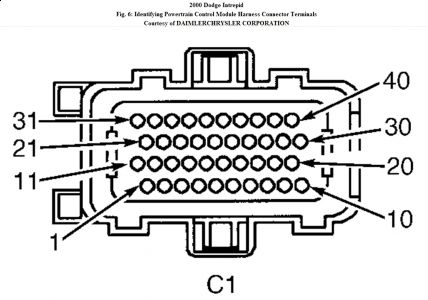
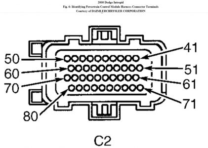
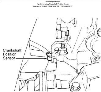
Testing 1. Turn ignition on. Using scan tool, select INPUTS/OUTPUTS and read current CKP state while cranking engine. If scan tool displays current CKP state PRESENT, go to next step. If scan tool does not display current CKP state PRESENT, go to step 23 . 2. Turn engine off. Disconnect CKP sensor connector. CKP sensor is mounted to passenger side of transaxle housing, above the differential housing. See Fig. 11 . Inspect connector for damaged pins, corrosion and loose terminals. Repair connector as necessary. If connector is okay, turn ignition on. Measure voltage between ground and Orange wire at CKP sensor harness connector. If voltage is less than 7.5 volts, go to next step. If voltage is 7.5-8.5 volts, go to step 10 . If voltage is more than 8.5 volts, repair short to voltage in Orange wire. Fig. 11: Locating Crankshaft Position Sensor Courtesy of DAIMLERCHRYSLER CORPORATION 3. Turn ignition off. Ensure CKP sensor is still disconnected. Disconnect PCM connectors. PCM is located on left side of engine compartment, between Power Distribution Center (PDC) and Transmission Control Module (TCM). See Fig. 2 . Visually inspect connectors for corroded, damaged, pushed-out or miswired terminals. Repair connectors as necessary. If connectors are okay, measure resistance of Orange wire between CKP sensor harness connector and terminal No. 44 at PCM C2 harness connector. See Fig. 6 . If resistance is less than 5 ohms, go to next step. If resistance is 5 ohms or more, repair open in Orange wire. 4. Measure resistance between ground and Orange wire at CKP sensor harness connector. If resistance is 5 ohms or more, go to next step. If resistance is less than 5 ohms, repair short to ground in Orange wire between CKP sensor and PCM. 5. Turn ignition off. Measure resistance between Black/Light Blue wire and Orange wire at CKP sensor harness connector. If resistance is 5 ohms or more, go to next step. If resistance is less than 5 ohms, Orange wire is shorted to Black/Light Blue wire. Repair wiring as necessary. 6. Turn ignition off. Ensure CKP sensor is still disconnected. Reconnect PCM connectors. Turn ignition on. Measure voltage between ground and Gray/Black wire at CKP sensor harness connector. If voltage is less than 7.5 volts, go to next step. If voltage is 7.5-8.5 volts, signal circuit (Gray/Black wire) is shorted to 5-volt to 8-volt supply circuit (Orange wire). Repair wiring as necessary. If voltage is more than 8.5 volts, repair short to voltage in Gray/Black wire. 7. Turn ignition off. Measure resistance between ground and Black/Light Blue wire at CKP sensor harness connector. If resistance is less than 5 ohms, go to next step. If resistance is 5 ohms or more, go to step 20 . 8. Remove CKP sensor. Inspect tone wheel/flexplate for damage. Check slotted areas on tone wheel/flexplate for damage or any foreign debris. Ensure tone wheel/flexplate turns when engine is cranked. Repair or replace tone wheel/flexplate as necessary. If tone wheel/flexplate is okay, go to next step. 9. At this time, PCM is assumed to be defective. Replace PCM. 10. Ensure CKP sensor is disconnected. Measure voltage between ground and Gray/Black wire at CKP sensor harness connector. If voltage is less than 4.5 volts, go to next step. If voltage is 4.5-5.5 volts, go to step 17 . If voltage is 7.5-8.5 volts, Gray/Black wire is shorted to 5-volt to 8-volt supply circuit (Orange wire). Repair wiring as necessary. If voltage is more than 8.5 volts, repair short to voltage in Gray/Black wire. 11. Turn ignition off. Disconnect PCM connectors. PCM is located on left side of engine compartment, between Power Distribution Center (PDC) and Transmission Control Module (TCM). See Fig. 2 . Visually inspect connectors for corroded, damaged, pushed-out or miswired terminals. Repair connectors as necessary. If connectors are okay, measure resistance of Gray/Black wire between CKP sensor harness connector and terminal No. 32 at PCM C1 harness connector. See Fig. 6 . If resistance is less than 5 ohms, go to next step. If resistance is 5 ohms or more, repair open in Gray/Black wire. 12. Turn ignition off. Measure resistance between ground and Gray/Black wire at CKP sensor harness connector. If resistance is 5 ohms or more, go to next step. If resistance is less than 5 ohms, repair short to ground in Gray/Black wire. 13. Measure resistance between Gray/Black wire and Black/Light Blue wire at CKP sensor harness connector. If resistance is 5 ohms or more, go to next step. If resistance is less than 5 ohms, Orange wire is shorted to Black/Light Blue wire. Repair wiring as necessary. 14. Ensure ignition is off. Reconnect PCM connectors. Measure resistance between ground and Black/Light Blue wire at CKP sensor harness connector. If resistance is less than 5 ohms, go to next step. If resistance is 5 ohms or more, go to step 20 . 15. Remove CKP sensor. Inspect tone wheel/flexplate for damage. Check slotted areas on tone wheel/flexplate for damage or any foreign debris. Ensure tone wheel/flexplate turns when engine is cranked. Repair or replace tone wheel/flexplate as necessary. If tone wheel/flexplate is okay, go to next step. 16. At this time, PCM is assumed to be defective. Replace PCM. 17. Turn ignition off. Measure resistance between ground and Black/Light Blue wire at CKP sensor harness connector. If resistance is less than 5 ohms, go to next step. If resistance is 5 ohms or more, go to step 20 . 18. Remove CKP sensor. Inspect tone wheel/flexplate for damage. Check slotted areas on tone wheel/flexplate for damage or any foreign debris. Ensure tone wheel/flexplate turns when engine is cranked. Repair or replace tone wheel/flexplate as necessary. If tone wheel/flexplate is okay, go to next step. 19. At this time, CKP sensor is assumed to be defective. Replace CKP sensor. 20. Remove CKP sensor. Inspect tone wheel/flexplate for damage. Check slotted areas on tone wheel/flexplate for damage or any foreign debris. Ensure tone wheel/flexplate turns when engine is cranked. Repair or replace tone wheel/flexplate as necessary. If tone wheel/flexplate is okay, go to next step. 21. Measure resistance of Black/Light Blue wire between CKP sensor harness connector and terminal No. 43 at PCM C2 harness connector. See Fig. 6 . If resistance is less than 5 ohms, go to next step. It resistance is 5 ohms or more, repair open in Black/Light Blue wire. 22. At this time, PCM is assumed to be defective. Replace PCM. 23. Turn ignition off. Visually inspect related connectors and wiring harness. Repair connectors and wiring harness as necessary. If connectors and wiring harness are okay, go to next step.
4/1/2010 ...


Thursday, April 1st, 2010 AT 1:11 PM


