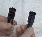
That is correct. Snapon Tool Company had about a $50,000.00 engine analyzer about 12 years ago that could generate just about any sensor signal so you could see what it normally looked like, but you could learn the same thing from any text book. Not many shops bought them because of their limited value. They could have actually been of more value to a school, but in my classes we never needed to know all those details, partly because we weren't going to make a diagnosis that way, and partly because the computer is already checking those signals, and it will tell us when there is a problem with that circuit.
I forgot to mention last night that in most applications you're going to find some kind of metal disc with multiple groups of notches that are detected by the crankshaft position sensor. On some Chrysler products, for example, there will be three sets of four notches for a V-6 engine, but those only tell the computer when a pair of pistons are coming up on top dead center. You also need pulses from the camshaft position sensor to tell it which two pistons are coming up on top dead center. On other models, there could be four notches, four notches, then three notches. With the three notches, the computer figures out when piston number one is coming up on top dead center. Those systems use ignition coil packs that have one coil to fire two cylinders at the same time, one on the compression stroke, and the "waste spark" on the other cylinder on its exhaust stroke. You don't need a camshaft position sensor when the engine uses a distributor because the distributor decides which one cylinder is going to get the next spark.
The point of this sad story is when rotating the crankshaft by hand, those notches are pretty far apart, so this is a lot of work to see if the signal voltage changes. When we experiment this way with reading signals, we're more likely to do it with anti-lock brake wheel speed sensors. Those develop around 45 to 60 pulses per revolution so it's easy to read something, but here again, the exact voltage is irrelevant. Digital voltmeters are only accurate on the AC Volts scales when reading a 60 hertz sine wave. They are totally inaccurate at other frequencies, and the voltage of the signals depends on wheel speed, just like with other magnetic sensors and generators. Also, when these position sensors have three wires, meaning there's a bunch of electronic circuitry inside them, they develop square=wave signals. Digital meters do not like anything other than nice smooth sine waves. The only meters that hold any value are those that can read frequency, but that still has no meaning unless you can read all four wheels at the same time with four meters. That is what the computer does, and we can see that with a scanner. The only value in testing the signal with a meter is to know whether you have something or nothing. When you have something, there is still a lot more the computer checks for to know when to set a fault code.
To get back to your original problem, one thing I forgot to mention is for some of these magnetic sensors, the air gap can be critical. When you have multiple repeat failures, it could just be bad luck with one replacement brand, or you may need to look for a mechanical issue related to that sensor. Examples of mechanical problems include that air gap, or a broken tone ring or whatever metal piece the sensor is detecting. Most crankshaft position sensors have a type of mounting bracket that you just bolt on and you're done. A few have slotted mounting holes to allow for adjustment. When you see those slotted holes, there is a procedure to set that air gap. I had a dozen that I was too smart to have to follow that procedure. The 13th one came back on a tow truck two weeks later with a fault code for that sensor, and a crank / no-start condition. I replaced the sensor, but setting the air gap as instructed probably would have solved the problem. So much for being smarter than the engineers.
Wednesday, January 27th, 2021 AT 11:03 AM
(Merged)


