Thursday, January 2nd, 2025 AT 9:12 AM
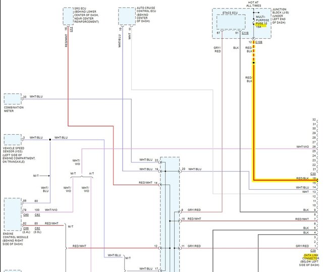
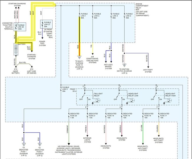
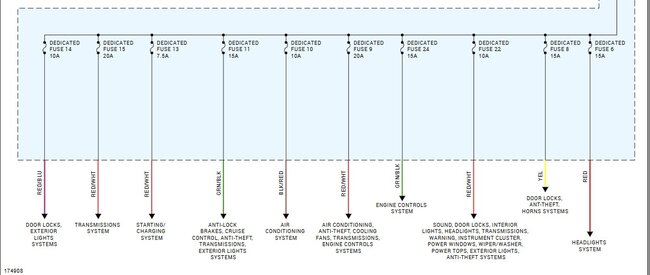
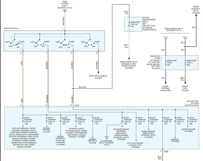
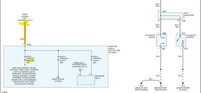
A few months ago, I got mad at my boyfriend, and I found his car and took all of the relays from the fuse box under the hood of the car. When he realized I had taken the relays he decided to jump them with wire to get the car home. He got the car started and drove it home and turned it off. He later that day again started the car and moved it and turned it off. That evening, I gave him back the relays and he put them back in their spaces under the hood. Only now the car just cranks and cranks but won't start. There is no power to the fuel pump although the pump is good. No power to the coils either. There is no power to the odb port. But there is also no security light on the dash at all either. Even when u initially turn the key to accessory and all the lights come on there isn't any security light that lights up.
