Good morning,
The evaporator freezing up is the issue. Can you give me the high and low side pressure readings while it is running to be sure the pressures are correct? The low side pressure switch should kick out the compressor before the system freezes up.
There is also a cycle switch for the compressor on the dryer that should disengage the compressor before freezing up.
Roy
Heating and A/C Operation
The purpose of the heating and A/C system is to provide heated and cooled air to the interior of the vehicle. The A/C system will also remove humidity from the interior and reduce windshield fogging. Regardless of the temperature setting, the following can affect the rate that the HVAC system can achieve the desired temperature:
* Recirculation actuator setting
* Difference between inside and desired temperature
* Difference between ambient and desired temperature
* Blower motor speed setting
* Mode setting
* Auxiliary HVAC settings
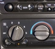
The manual HVAC system is a dual temperature zone system. There are 2 separate air temperature levers. Moving the air temperature levers to the upward position diverts most of the airflow through the heater core, which increases the outlet air temperature. Moving the air temperature levers to the most downward position diverts most of the airflow around the heater core, which decreases the outlet air temperature. The right air temperature actuator controls the duct air temperature flowing through the center console to the second row seating passengers. The air temperature offset can be as much as 16.7°C (30°F).
Pressing the A/C button enables the HVAC control module to request A/C compressor engagement and turn ON the A/C button LED. The HVAC control module sends a GMLAN message to the Powertrain Control Module (PCM) for A/C compressor engagement. The PCM will provide a ground for the A/C compressor relay enabling it to close its internal contacts to send battery voltage to the A/C compressor clutch coil. The A/C compressor diode will prevent a voltage spike, resulting from the collapse of the magnetic field of the coil, from entering the vehicle electrical system when the compressor is disengaged. Defrost and Defog mode selections will request A/C operation but not turn ON the A/C LED.
The following conditions must be met in order for the A/C compressor clutch to turn ON:
* Ambient air temperature above 2°C.
* A/C low pressure switch signal circuit is grounded.
* A/C refrigerant pressure sensor parameter is less than 3234 kPa.
* A/C compressor temperature switch contacts are closed.
* PCM receives an A/C request from the HVAC control module.
* Engine coolant temperature (ECT) is less than 124°C.
* The engine RPM is less than 5800 RPM.
The sensor information is used by the PCM to determine the following:
* The A/C high side pressure
* An A/C system load on the engine
* An excessive A/C high side pressure
* The heat load at the A/C condenser
The A/C compressor has an A/C compressor temperature switch. This switch protects the compressor from over heating. The switch interrupts power to the compressor clutch coil. When the compressor core temperature rises above 124°C (255°F) the switch opens, disabling the compressor clutch coil. When the temperature lowers to 120°C (248°F) the switch closes, enabling the compressor clutch coil. This switch is not a serviceable part, it is integral to the A/C compressor.
Once engaged, the compressor clutch will be disengaged for the following conditions:
* Ambient air temperature is less than 1°C (35°F).
* A/C compressor temperature switch contacts are open.
* Throttle position is 100 percent.
* The A/C low pressure switch is open.
* A/C high side pressure is more than 1931 kPa.
* A/C low side pressure is less than 151 kPa (22 psi).
* Engine coolant temperature (ECT) is more than 124°C.
* Engine speed is more than 5,800 RPM.
* Transmission shift
* PCM detects excessive torque load.
* PCM detects insufficient idle quality.
* PCM detects a hard launch condition.
Cycle switch
Air Conditioning Cycling Switch Replacement
Removal Procedure
1. Disconnect the electrical connector from the A/C low pressure switch.
ImageOpen In New TabZoom/Print
2. Remove the A/C low pressure switch from the accumulator.
3. Remove the O-ring and discard.
Images (Click to make bigger)
Wednesday, March 17th, 2021 AT 5:15 AM


