FUEL SYSTEM PRESSURE TEST TBI 1. Turn ignition off for 10 seconds. Turn ignition on, and listen at fuel tank for fuel pump operation. Pump should run 2 seconds (20 seconds on models with fuel module). If fuel pump runs, go to next step. If fuel pump does not run, go to step 7). 2. If fuel pump runs, turn ignition off. Verify fuel tank has fuel. Relieve fuel pressure. See FUEL SYSTEM PRESSURE RELIEF. Remove air cleaner, and plug air cleaner vacuum ports (if equipped). Disconnect fuel line between throttle body and fuel filter. Install Fuel Pressure Gauge (J-29658A) and Adapter (J-2968A-85) between steel fuel line and flexible hose, ahead of in-line fuel filter. 3. Turn ignition on, and note reading on pressure gauge. If fuel pressure is 9-13 psi (.63-.91 kg/cm 2 ), no problems are present. If pressure is less than 9 psi (.63 kg/cm 2 ), go to step 5). If pressure is greater than 13 psi (.91 kg/cm 2 ), turn ignition off, and bleed fuel pressure. Disconnect fuel return line downstream of pressure gauge. Insert return line into a gasoline container. 4. Turn ignition on. If pressure is now 9-13 psi (.63-.91 kg/cm 2 ), correct restriction in fuel return line between disconnected point and fuel tank. If fuel pressure is greater than 13 psi (.91 kg/cm 2 ), check for restricted return line (including fuel filter) downstream of pressure gauge. If no restrictions are present, replace fuel pressure regulator (TBI 700) or fuel meter cover/pressure regulator (TBI 220). 5. Check for restricted line between in-tank fuel pump and pressure regulator. If fuel line is okay, disconnect injector connector. Turn ignition on. Gradually pinch fuel pressure gauge outlet hose. Note pressure. 6. If pressure is greater than 13 psi (.91 kg/cm 2 ), replace fuel pressure regulator (TBI 700) or fuel meter cover/pressure regulator (TBI 220). If pressure is less than 9 psi (.63 kg/cm 2 ), check for faulty fuel pump or incorrect part. Check fuel pump coupling hose and pump inlet filter in fuel tank. On models with dual fuel tanks, check for faulty fuel tank selector valve and meter switch. 7. Apply 12 volts to fuel pump test connector. For fuel pump test connector location, see underhood engine component views under COMPONENT LOCATIONS in SYSTEM/COMPONENT TESTS article in this section. If fuel pump now runs, repair open in fuel pump relay drive or power circuit or repair faulty fuel pump relay. To test relay, see SYSTEM/COMPONENT TESTS article in this section. 8. If fuel pump does not run with 12 volts applied to fuel pump test connector, repair open in fuel WARNING: Begin fuel system trouble shooting and diagnosis with fuel system pressure test. Relieve fuel system pressure before disconnecting any components or installing fuel pressure gauge. CAUTION: DO NOT pinch off fuel return line completely. DO NOT allow fuel pressure build-up to exceed specification, as damage to fuel pressure regulator may occur.
Check for vacuum at PCV, remove PCV frm hose, any vac? If low check for slit hose, or a common problem on high milage vehicles is TBI carboned up at the base. Remove TBI and inspect the bottom, it may be gunked up. You may have a vacuum leak, get a can of spray gumout, spray the vac lines and maniflod area, when the idle changes, youve found the leak! You want the engine running and spray on the outside but do direct the stream onto the hoses, if it is a vacuum leak, the engine idle will change speed, then you have detected a leak, repair the vacuum leak and see how it runs! If that doesnt do it, you may need a new idle air control valve, it's bolted to the throttlebody
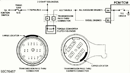
Torque Converter Clutch (TCC) Solenoid Disconnect harness connector to TCC solenoid. Measure resistance between TCC solenoid terminals. SeeFig. 10-Fig. 15 . Solenoid resistance should be greater than 20 ohms.
TIMING CONTROL SYSTEMS (C-4 & C-5) C-4, Electronic Spark Timing (Gasoline Engines) An open or short to ground in Electronic Spark Timing (EST) or by -pass circuit will cause ECM to turn on Malfunction Indicator Light (MIL) and confirm fault causing Code 42 is present. Refer to appropriate TESTS W/CODES article in this section. C-5, Electronic Spark Control (ESC) Circuit (Gasoline Engines Except 2.5L, 4.3L Turbo & Vehicles With 4L60E Transmission) 1. An open or short circuit on ESC wire to ECM will cause a loss of 12-volt ESC controller signal. This will cause ECM to fully retard ignition timing. 2. If a scan tester is available, connect tester to Data Link Connector (DLC). Using a metal object, tap on engine next to knock sensor and note knock parameter. Knock should be indicated on scan tester. 3. If a scan tester is not available, backprobe ECM ESC signal terminal with a DVOM. With engine idling, 8-12 volts should be present at this terminal. Using a metal object, tap on engine close to knock sensor. Voltage signal at ECM terminal should drop to zero volts, and return when knock signal ceases. 4. If signal does not respond as described, check knock sensor signal to controller signal. On vehicles equipped with automatic transmission, it may be necessary to place transmission in Drive for timing change to occur. See KNOCK SENSOR under ENGINE SENSORS & SWITCHES.
POSITIVE CRANKCASE VENTILATION Required Service - The PCV system may require service for obstructions if any of the following conditions exist: à   Rough Idle à   Stalling or Slow Idle Speed à   Oil Leaks à   Oil in Air Cleaner à   Sludge in Engine A leaking PCV valve or hose could cause: à   Rough Idle à   Stalling à   High Idle Speed If engine idles roughly, check for clogged PCV valve and for plugged or broken PCV hoses BEFORE adjusting idle. Check correct PCV valve application to ensure the correct valve is fitted. Replace PCV valve if required. Checking PCV Valve Function (Except 2.5L) 1. Remove PCV valve from rocker cover. Run engine at idle. Place thumb over open end of valve to check for vacuum. If there is no vacuum at valve, check for obstruction in manifold port, hoses or PCV valve. Repair or replace as necessary. 2. Turn engine off. Remove PCV valve. Shake valve and listen for rattle of check valve inside PCV valve. If a clear rattle is not heard, replace PCV valve. 3. Visually inspect valve for varnish or deposits that may make PCV valve operation sticky, restricted or incompletely seated. Replace if necessary. 4. Engine must be sealed for PCV system to function as designed. If leakage, sludging or dilution of oil is noted and PCV system is functioning properly, check engine for cause and repair as required to ensure PCV system will continue to function properly. 5. Since an engine operating without any crankcase ventilation can be damaged, it is important to replace PCV valve and air cleaner breather at regular intervals (at least every 30,000 miles). Check all hoses and clamps for failure or deterioration.
ELECTRONIC SPARK CONTROL (ESC) MODULE REMOVAL & INSTALLATION Turn ignition off. Remove bracket-to-firewall screws. Rotate bracket to access ESC module. Disconnect ESC module harness connector. Remove ESC mounting screws and remove ESC. To install, reverse removal procedure. NOTE: On models equipped with external ESC module, ESC is located on bracket behind distributor, mounted to firewall. The other thing to check on high mileage trucks is the timing chain, it may have jumped by 1 tooth and this will allow it to run, but real diesely like1 Check timing marks and #1 at TDC, Compression you gave is low...150 or so is the avaerage.

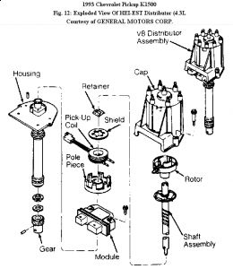
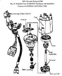
Installation 1. To install, reverse removal procedure. To insure correct timing of distributor, install with rotor correctly positioned as it was before distributor was removed. 2. If engine was cranked after distributor was removed, remove No. 1 spark plug. Place finger over No. 1 cylinder spark plug hole. Crank engine slowly until compression is felt. Align timing mark on pulley to "0" on engine timing indicator. Turn rotor to point to cylinder No. 1 spark plug tower on distributor cap. Complete distributor installation. Start engine and check ignition timing.


If it has esc, it's on a brackett behind the distributor, mounted to firewall.
Sunday, January 5th, 2020 AT 5:55 PM
(Merged)


