Check Engine light on since 2013?

Tiny
CODYBTUCKER
  • MEMBER
  • 19 POSTS
I will take a picture of the two damaged connectors tomorrow and send them to you.
The new distributor never shut down, so I bet the original distributor is doing what you said when it gets hot and expanding causing a disconnection - I actually don't understand it or can't visualize it, but I believe it.

Below are the ohms readings of the male contact or pin that is part of the idle speed control motor sensor that the harness connects to:
PIN 2 GR 4500
PIN 3 gnd used to do readings
PIN 4 G 0 ohms
PIN 5 Br 450
PIN 6 GR 4500

Below are the ohms readings from the volume air flow sensor male pins identified by the wires color from the harness because the pins don't match what the diagram A35 shows: I am showing two readings because they were not consistent.
GL 3200 / 2400
Red 2300 / 1600
GR 2300 / 1600
GB gnd used for all readings
GY 4100 / 2600
GO 1900 / 900

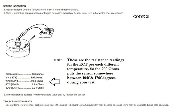
ECT ohms reading:
YG 900

PIN 17 in ECM with key on but engine not running was.3 volts.
I had the engine coolant temperature harness unplugged and the volume air flow sensor harness unplugged during that check. I'm not sure if I was supposed to run an ohm's check from PIN 17 to PIN 5, but they are both a brown wire (Br) and it seemed like one of those diagrams did a check like that.

I will try to check ECM pins 8 (IATS) and 20 (ECTS) again as they were both 1.1 volts last time I checked them. I will also try to check ECM pins 13 and 23 for the 5 volt reference.

The six wires in the harness going to the distributor are difficult to identify - seem like 4 of them are a gray or blue gray color and then there's one green with the yellow stripe and one orange with the yellow stripe. I might try to find one or two of them at the engine control module to see the signal.
Was this
answer
helpful?
Yes
No
Thursday, October 3rd, 2024 AT 11:03 PM
Tiny
AL514
  • MECHANIC
  • 4,795 POSTS
The crank and cam sensors inside the Distributor are pick up (variable reluctance) type of sensors, so they are a coil of wire and when a part of a trigger wheel passes by the pick up for the sensor it sends a signal, now it could also be the transistor getting hot inside and failing as well, this is a diagram of the Distributor, the Ignition Power Transistor is a solid state device, which is inside an ignition module inside the Distributor, but long story, short, it can act with the same hot/cold fault.

***Now onto the idle motor sensor, the resistance reading is within spec, so its not open circuit, 4.5k Ohms from pin 2 to pin 3, then also pin 6 to pin 3 is correct. I would say on this, the connector needs to be repaired or replaced. ***I would do this first and see if it resolves the other codes.

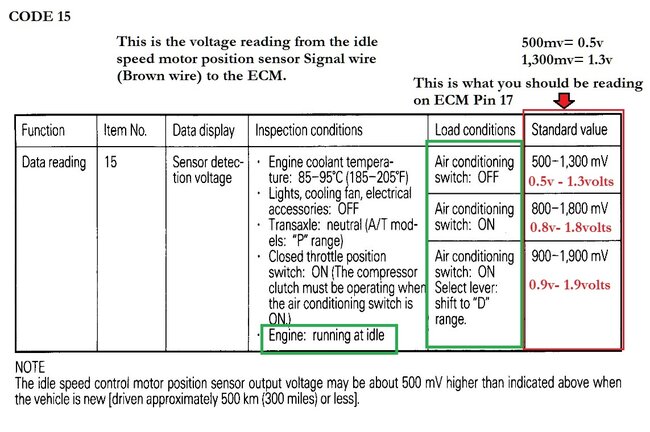
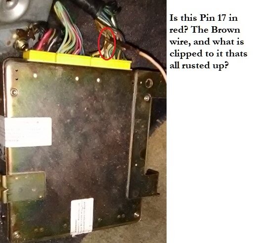
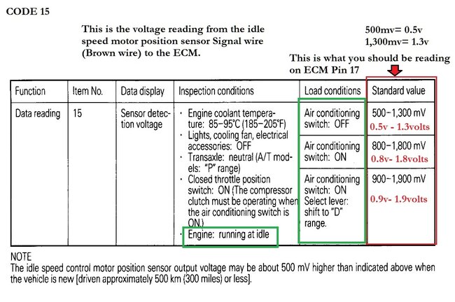
Pin 5 being your signal wire, 450 ohms is most likely the position of the motor at this time, you are correct that Pin 5 is the same wire that goes to pin 17 of the ECM, you can unplug the ECM and the idle motor and check the resistance from pin 5 to pin 17, you should have roughly 5 ohms or less since you are just checking from one end of the wire to the other end. Diagram 2 below is the voltage reading you should have on pin 17 with everything plugged in and engine idling.

Did you take the new Distributor back out? Sorry we are just testing so many components here Im trying to keep track of where we are at.

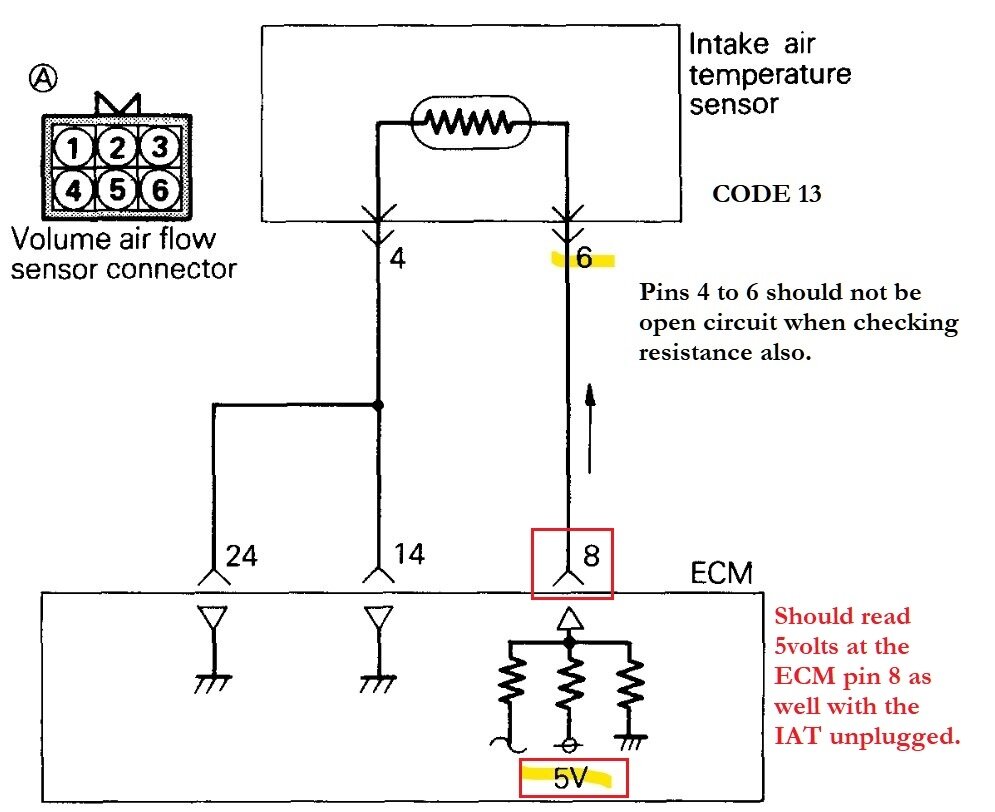
The reason I wanted you to check for 5volts on pin 8 and 20 was to make sure that either the IAT or ECT sensors were not shorted out and effecting the other sensors, if one is shorted out and pulling down the 5volts, it can cause other sensors to set codes as well.
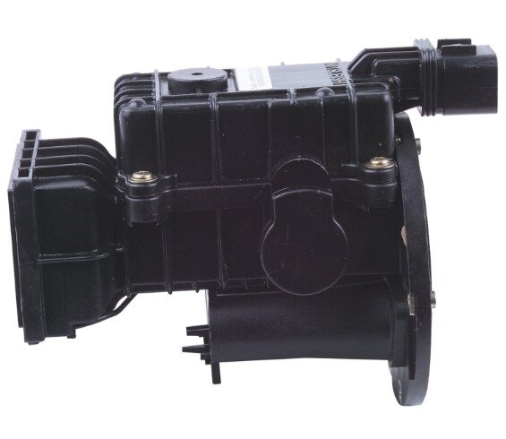
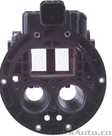
This is the Air Volume sensor youre dealing with, its a pretty complex sensor for a 1993. Its also about $120 from rockauto. Just resistance readings jumping around like that can be caused by potential solder joint issues inside, since you had steady readings on the other sensor I dont think its a multimeter issue, but resistance will jump around like that when the circuit being tested doesnt have a good complete circuit,

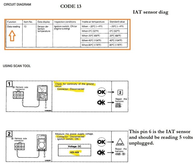
whats difficult about this sensor is with service info they want you to see what a scan tool is reading from the sensor compared to the actual temperature. For code 13 they have you check scan tool data temperature reading, then check the ground for the sensor and then just the 5volt ref, and thats it, (diagram 5). So youre previous check of the unplugged 5volt ref that was low, is really our only clue as to what might be setting the code.

You can do the same check on the wire from ECM pin 8 to IAT pin 6, except with the colors being incorrect, service info doesnt help us much, the only thing you can really do is see if ECM pin 8 has a resistance reading to one of the 6 wires of the connector.

The Code 21 ECT info is on diagram 7.
I feel terrible to be overloading you with so much info at once here as well, and if we are dealing with a low 5volt reference causing these codes, that opens up a whole other can of worms, But do your best, ECM pin 23 should remain at 5v as well.
Sorry again for the long posts, but do the idle motor connector repair first.
Was this
answer
helpful?
Yes
No
Friday, October 4th, 2024 AT 3:31 PM
Tiny
CODYBTUCKER
  • MEMBER
  • 19 POSTS
Key on and engine off with VAFS harness disconnected, ISC MOTOR POSITION SENSOR harness disconnected and ECT harness disconnected readings at ECM:
PIN 13 - 5 volts
PIN 23 - 5 volts
PIN 8 - 3.9 volts to IAT sensor
PIN 20 - 3.9 volts to ECT sensor
Last time I checked PIN 8 and PIN 20 with the harnesses connected they were the same at 1.1 volts with key on engine off and now they're the same at 3.9 volts with the key on and the harnesses disconnected and these two pins are right next to each other at the ECM. Could these two (pins 8 and 20) be shorted together between the engine control module and the sensors.
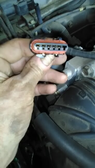
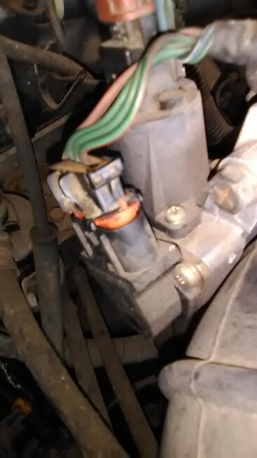
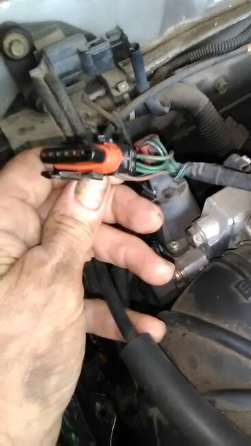
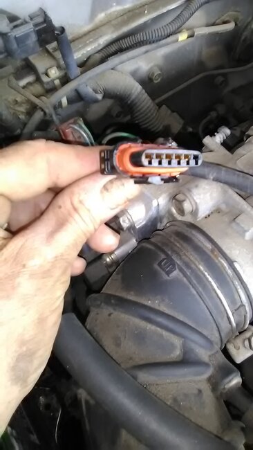
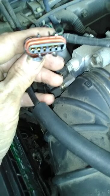
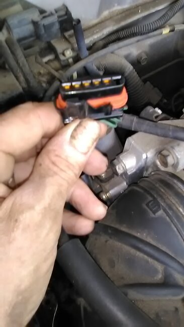
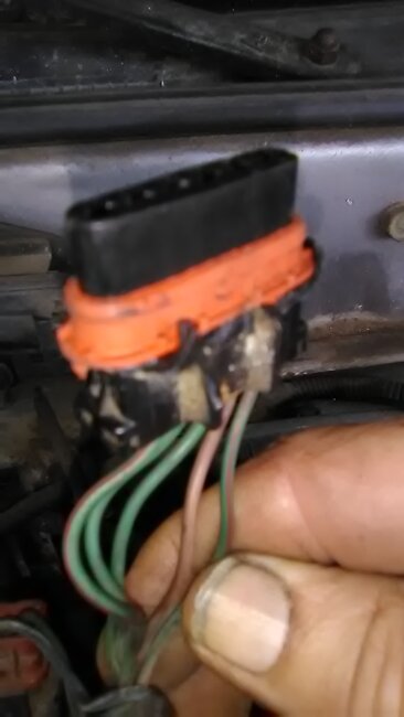
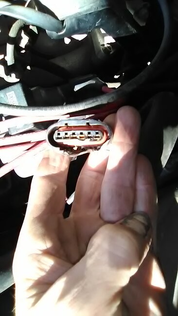
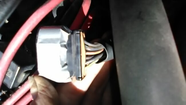
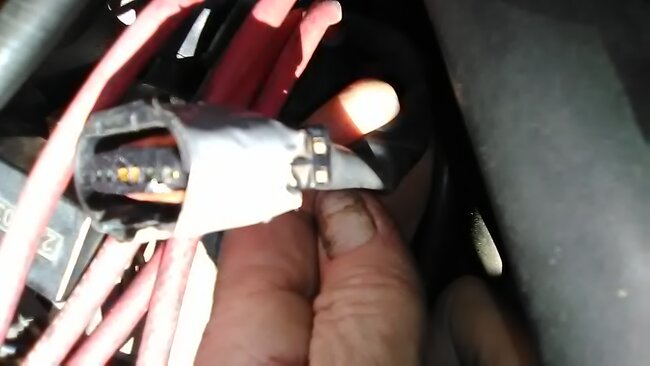
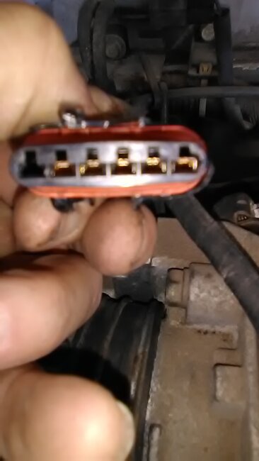
I attached photos of the idle speed control motor position sensor harness connector for you to evaluate the damage, but I doubt if it's the problem because these codes were there in 2013 and I doubt if the harness had much if any damage in 2013.
I was going to try to read the codes again with the ohms reading, but there's four wires in the diagnostic connector and I couldn't find where the diagram indicate which wire to connect to which lead from the multimeter. I believe only one of the wires is dark and the other three are either creamy or white color.
Was this
answer
helpful?
Yes
No
Friday, October 4th, 2024 AT 10:23 PM
Tiny
CODYBTUCKER
  • MEMBER
  • 19 POSTS
I believe I am the cause of the car shutting off when it gets hot because I traded a battery that I unsuccessfully tried to recondition (I'm not even sure reconditioning a battery is possible) for a used battery that would start the car - only since that battery swap has this problem of the car shutting down been in existence. Batteries go bad over time and they must be charged by a charger or used and charged by the alternator or they go bad faster, and this car only drives about a hundred miles every 6 months - keeping a new battery in it, it is kind of like the mechanic shop that replaced a working fuel pump in the car to get the check engine light to go out and charging me $55 for the inaccurate diagnostics and over $200 for the pump and labor - I understand all of that was my fault not their fault.

The first thing I noticed when the car shuts down from heat is all the lights in the instrument warning panel come on and the engine still cranks while it's hot (that might rule out the ECM since the check engine light is on immediately and the car cranks with all the instrument panel warning lights on), but it will not start for about an hour and that might vary with atmospheric temperature. Some distributors may react differently to battery hot and over and under voltage issues caused by batteries, and that maybe why the one distributor wouldn't shut down the car, but it wouldn't start when the battery got hot and the other distributor shuts down the car. I feel bad about all the problems that are directly or indirectly my fault and causing you diagnostic complications.
Was this
answer
helpful?
Yes
No
Saturday, October 5th, 2024 AT 4:46 AM
Tiny
AL514
  • MECHANIC
  • 4,795 POSTS
Oh dont feel bad, you wouldnt believe some of the messes we get into here, I have spent months with certain people trying to explain even the simplest things to them, so youre all good, no worries.

So as for your question on the two sensors possibly having their wiring shorted together, yes that can absolutely happen, to check that, unplug both sensors, and unplug the ECM connector they go to and just check pin 20 and pin 8 at the ECM connector for continuity between the two, there shouldnt be any reading between the two of them, with both ends
of the circuit open while unplugged they should read OL on the meter.

Another test you can do is with them both still unplugged, check for continuity to ground (Battery Negative) on either wire, there should also be no reading from that test. If you read anything, the wires can be shorted to ground somewhere, its common to find wires melted together at location where they might be touching the exhaust or a contact location where they have been rubbing on metal over the years and they short out that way.

A corroded connector can also short circuits together, if water or some other liquid has gotten into something like a bulk connector, in that case you will find a bunch of green or white crusty corrosion inside the pins of the connector. Even a pin hole of a wire can corrode inside, and the corrosion can just grow inside the wire insulation breaking the copper strains, those are difficult to find because you cant actually see the corrosion.
So following the wiring in the harness from a sensor will sometimes lead you to a location where the wiring is just a complete mess.

From your readings it sounds like Pin 13 & 23 are a different voltage regulator inside the ECM and pin 8 and 20 share a different 5volt regulator, or most likely you would be reading the same 3.8 volts on 8 and 20 as well.

The best thing for you to do if the vehicle is not going to be driven for a while is unhook the negative battery cable, that will prevent it from draining as fast.
When a battery goes bad, it can be the result of either being tightened down too much, in which the cells inside the battery actually get crushed and shorted together, many people tighten the battery hold down too much, you can tell when you see a battery that has the top squished down and the sides are bulging out. That happens a lot when places like auto parts stores replace the battery for a customer and over tighten it.
And batteries also just age, and become sulfated inside which also shorts out the cells inside, there are 6 cells in a 12v lead acid battery, 2volts per cell, so when 2 cells get shorted together, the battery can no longer be fully charged or hold a charge.
A bad battery will also eventually take the Alternator out, due to it being overworked trying to charge a bad battery.

With that said, the 3.8 volts is an issue, if you do not find a wiring problem, we will have to check the ECM powers and grounds for any voltage drop while the vehicle is running with some electrical loads on.

The ISC motor sensor gets its 5volts from pins 13 and 23, and the resistance reading of the sensor was within spec, so these are the voltage values you should expect on ECM pin 17 while its running, I know I posted this already, but something else to recheck since we seem to be getting to the bottom of seeing what the causes of some of these codes are. It looks like there are just possibly multiple problems which is not surprising.

Look for rodents nests too, vehicles not driven much seem to always have more rodent damage to wiring harnesses. Ive seen so many those. Especially under the passenger side dash where the blower motor is, they love to make nests in those areas, and they eat the insulation on the wires because it contains a chemical they like the taste of. Pretty gross.
Was this
answer
helpful?
Yes
No
+1
Saturday, October 5th, 2024 AT 5:15 PM
Tiny
CODYBTUCKER
  • MEMBER
  • 19 POSTS
There is some white stuff that was like a cream when I first saw it inside of a connector that connects two wires that go to the bottom of the radiator reservoir or overflow. I will try to clean that connector if possible. I should have asked you because I was wondering if that was supposed to be in there as some kind of lubricant. Would it be okay to just disconnect that possible corroded connection and see if it is causing problems after I run the checks on PIN 17. I do or did have a rodent problem because there were peanut hulls near my volume air flow air inlet and it looked like it tried to start a nest inside of the air filter container but the air filter blocked the rodent from going any further - where the sensors are. I tied the guard to that air inlet up against it so that the rodent couldn't get in behind it like it was previously.
Was this
answer
helpful?
Yes
No
Saturday, October 5th, 2024 AT 10:28 PM
Tiny
AL514
  • MECHANIC
  • 4,795 POSTS
Usually corrosion inside connectors will turn into a crusty type of corrosion that is flaky and is what we call the green crustys, but it can be white in color too, what your describing sounds more like someone put dielectric grease into the connector to prevent moisture from getting in, what most people dont understand about dielectric grease is that it does not conduct electricity, they seem to think it does, but its safe to use because it wont corroded electrical connectors. You can get a spray can of electrical connector cleaner at autozone or other auto part stores, thats safe to spray right into connector pins and it will clean and then dry not leaving any residue behind. So you may want to check any other bulk connectors in the engine compartment for corrosion inside, this low voltage issue might be a result of a main power feed to the ECM not suppling full voltage or there could be resistance in a circuit, Ill check on how many powers and grounds there are to the ECM as well.

Those two wires going to the reservoir may be for a float or something that triggers a low coolant warning light.
For the rodent damage, they will eat right through an air filter too, what guard are you referring to that you tied up to the air flow sensor?

I will look and see if I can find the two wires to the coolant res, you can unplug it and just see if the low coolant light comes on, I dont think it will have any effect on starting or running. But if there was rodent damage in that location, I would keep looking for more signs of it throughout the vehicle, mice can get into the smallest locations, usually you can smell it when they get into the interior of the vehicle, I cant tell you how many rodent nests Ive taken out of vehicles, probably hundreds, especially when I was working for a Subaru dealership that was out in the county. I was finding them almost everyday.
Was this
answer
helpful?
Yes
No
Sunday, October 6th, 2024 AT 3:13 PM
Tiny
CODYBTUCKER
  • MEMBER
  • 19 POSTS
Br wire from the (ISC) Idle speed control motor position sensor - PIN 17 readings at ECM: volts stayed.4 volts with air conditioner off and air conditioner on. I know that the fan at the radiator kicked on but I'm not sure what the parameters are or how to know if the compressor was on, which was a parameter for the third measurement. Seems kind of mute anyway because 0.4 is below the allowable tolerance which the diagram indicated from.5 to 1.3 volts and goes up to.8 to 1.8 with air conditioner on and 0.9 to 1.9 with compressor on. The car engine RPM was idling at 950, dropped to 900 when I turn the fan on, and drop to 700 when I turn the air conditioner on, but the car never died out.
I have not been able to get the car to start since I did that test after turning the car off. The instrument warning panel lights come on when I turn the key on, and the car cranks every time I turn the key on, but it has not started since I did that air conditioning test. I will push it out in the sun and try to start it tomorrow. I have not used the air conditioner for over a decade unless I was at high RPM on the freeway or somewhere where I never idled because even 10 or 20 years ago it would almost die out when the air conditioner was turned on at idle, and sometimes it did die out and was hard to start.
There is a guard for the volume air flow inlet, but it was nowhere near where the actual opening was so I took it off from the manufactured location and put it right up against the opening and then I tied it in place to keep the rats or mice from accessing the filter in the volume air flow Component.
Was this
answer
helpful?
Yes
No
Sunday, October 6th, 2024 AT 10:37 PM
Tiny
AL514
  • MECHANIC
  • 4,795 POSTS
Okay, putting the guard in front of the air flow meter will effect air flow into the engine, in fact those air filter boxes are designed in a way that causes the air flow to be more turbulent,
It sounds like the idle speed motor might not be moving like it should, Try removing the guard from the air intake boot area, and see if it will start, technically pressing the gas pedal will open the throttle plates allowing more air in, if that idle speed motor is the issue.
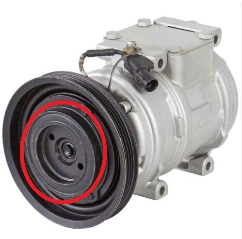
For some reason the engine cannot handle any kind of load on it such as the AC compressor. You should see the AC compressor clutch cycling on the front of the compressor, Ive marked it here in red, that center part should be cycling on and off when you have the AC on.
But you shouldnt have to push it into the sun to get it to start, try removing the guard first.
Also take a look at the throttle plates, see if there is carbon built up around the edges of the plate, you can move it open by hand; this starting issue is probably a result of the ECT sensor being out of range during a cold start up, thats the main sensor the ECM is looking at for fuel delivery when the engine is cold. So I think either moving it into the sun brings that sensor closer to a reasonable spec, or the ECM itself is warming up and has an internal problem on the circuit board, I assume you have another vehicle to get around?
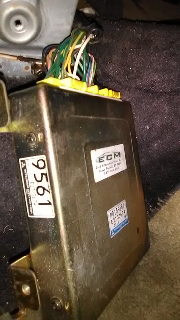
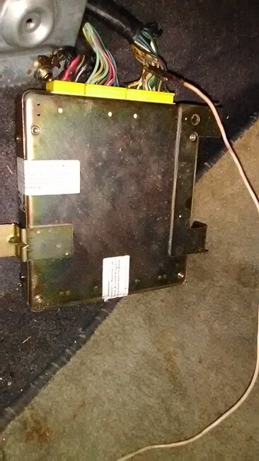
Can you post a picture of the ECM for me, you dont need to unplug it or anything, I just want to see which type it is. If you have trouble posting it here for whatever reason leave me an email and Ill contact you for the picture.
I also question the condition of the ignition system, ie spark plugs and wires, possibly some clogged fuel injectors as well. Or even old gas since youre having so much trouble starting it.
Was this
answer
helpful?
Yes
No
Monday, October 7th, 2024 AT 11:48 AM
Tiny
CODYBTUCKER
  • MEMBER
  • 19 POSTS
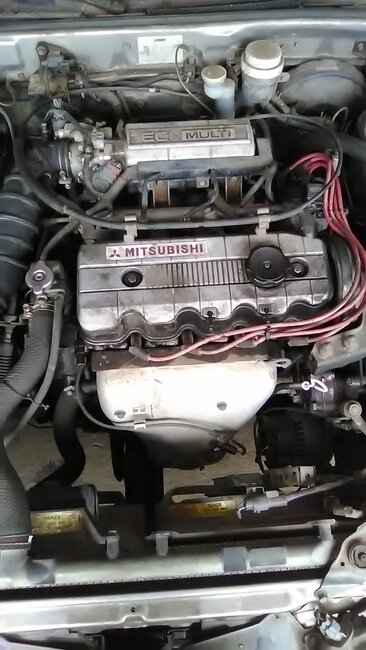
Two of the photos are of the engine control module both sides, two of the photos are of the throttle next to the idle speed control and the last photo is of the clutch or air conditioner part that you wanted me to look at because it is way down in there and I'm not sure when you say cycling on and off if that thing is spinning or moving in and out - I could not tell. Another strange thing that might be helpful is that the coolant temperature warning light, door ajar, brake and the battery warning light always came on when I turn the key on and now since we did the air conditioning test those lights do not come on when I turn the key on but after trying to start the car the lights then show up with the other warning lights (check engine, oil, seat belt).
Was this
answer
helpful?
Yes
No
Monday, October 7th, 2024 AT 10:13 PM
Tiny
AL514
  • MECHANIC
  • 4,795 POSTS
The front clutch on the AC compressor should be spinning and cycling on and off roughly every 8 seconds on these older ones. I can definitely see that is a remaned ECM.
Removing the guard in front of the air flow meter and checking the condition of the throttle plates would be what I would do next, you'll need to remove the air intake hose that goes to the throttle body but that should only be held in place by a hose clamp.

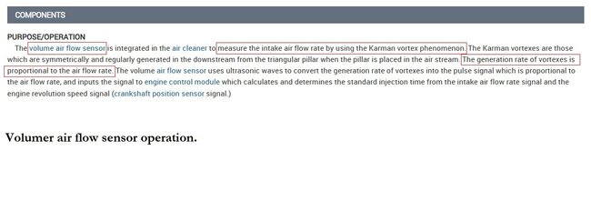
Something to note, and I will post the air volume sensor operation below because it signals the ECM by Frequency not a voltage reading and the vortex or turbulence of the incoming air is very import for the sensor to read correctly, and the **guard being in the way is not allowing that air turbulence,
the ECM calculates the amount of fuel to be delivered from the air volume sensor, using the other sensors such as the IAT and other temperature sensors to adjust that air/fuel mixture depending on engine and outside temperature.

The Coolant temperature warning light is most likely happening because of that voltage variation. With only 3.8volts on a 5volt reference circuit for such a critical sensor, and the load that the AC compressor put on the engine, (even if it didnt turn on because the ECM will adjust the idle according to the AC pressure sensor), may have just plainly over worked some other components. Because the car is not driven much at all, thats one of the worst things for a vehicle, is to sit, it effects so much.

So from here we can either diagnose the no start condition by checking for ignition spark to make sure the spark plugs are even firing, you can see if it will start with the air intake system cleared of any obstructions, such as that guard, at least temporarily.

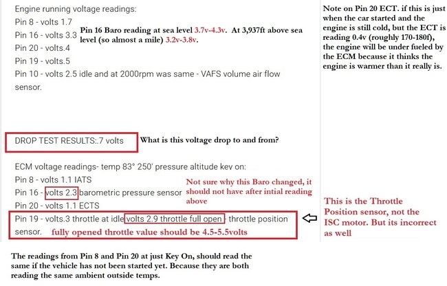
Diagram 3 below is some notes on your testing voltages, there are some sensors not reading correctly, The Baro reading should not have changed, since the key On values are different than the running values, I do wonder about this battery too.
But put the air flow guard back where it should be, check the battery voltage before starting the car, and see how low the voltage drops when cranking the engine. If it drops below 9-10volts during cranking its no good and needs to be replaced. A bad battery can cause Alternator problems that will eventually cause the ECM to fail.

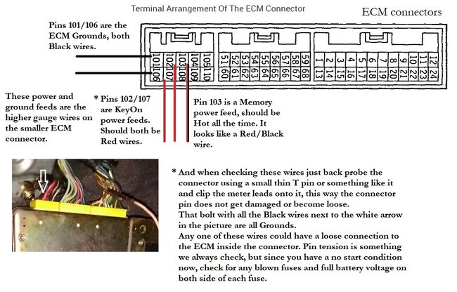
The ECM I can bench test if needed, but low voltage to the ECM during running or a wire connection issue (corrosion) will cause voltage drop especially while running because of the extra electrical loads. Even though you tested the wrong pin, 19 instead of 17, the throttle position sensor is not reading correctly at full throttle.
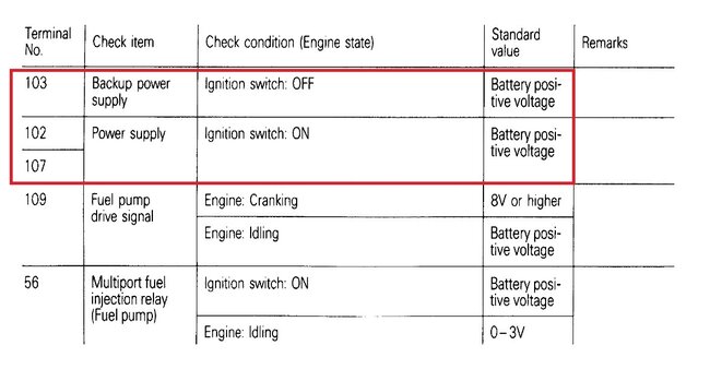
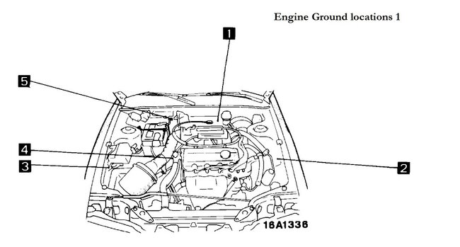
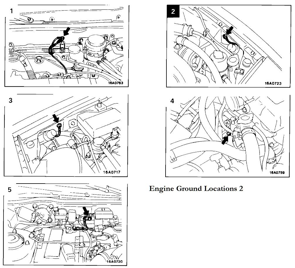
These are probably all related. Diagram 4 is the ECM battery voltage pins and 5, 6 are the Ground locations in the engine compartment to check for corrosion or broken wires, they should be cleaned as well.
Was this
answer
helpful?
Yes
No
Tuesday, October 8th, 2024 AT 9:56 AM
Tiny
CODYBTUCKER
  • MEMBER
  • 19 POSTS
The car cranks but it will not start, and it has only started doing this since the air conditioning fan and clutch were engaged. On the instrument warning panel lights, the door ajar light should be on and is not on and the brake light is on dim when it should not be on and the brake light goes bright when I engage the brake and sometimes when I turn the key on there are three lights and sometimes there are six lights and after turning the key to crank it defaults back to six lights in the instrument warning panel and all of this has started since you had me do the air conditioner test on the engine control module PIN 17 test that resulted in point 4 volts when it should have been.5 volts to 1.3 volts. I swapped the battery and the problem is the same. The five ground points that the diagram indicated as the eclipse engine grounding points all tested with what appeared to be the same appropriate ohms. Can there be a wire or wires from the air conditioner or air conditioning components that can tell the engine to shut down as soon as it starts (meaning it cannot ever start) and can be causing instrument warning panel light issues? Why is engine control module PIN 17 giving a steady.4 volts when it should have been climbing to.8-1.8 when the air conditioner was turned on. The air conditioner has been a problem with this car since before the engine control module went dead in January of 2013 and since ECM was replaced the check engine light to the best of my knowledge has been on. Many mechanics have looked at this car with this information, and either walked away scratching their heads or charged me money and amplified or increased the problems.
I remove the hose between the idle speed control engine position module and the volume air flow sensor, but you have to tell me why or what to do with it. I also remove the guard that was intended to keep the rodents out of the volume air flow sensor filter, but the car started many times with that guard in place and it still will not start now without the guard in place.
Was this
answer
helpful?
Yes
No
Wednesday, October 9th, 2024 AT 3:17 AM
Tiny
AL514
  • MECHANIC
  • 4,795 POSTS
I wanted you to check the throttle plates for any carbon build up, and you cant get to them without removing the air intake boot. If the ISC motor position should move when the AC is on to increase the engine idle because of the load the AC compressor puts on the engine, try unplugging the compressor clutch, it has a connector that goes to the clutch on the front.
Its possible the AC compressor is starting to seize up or there is a problem with the Compressor clutch or Clutch relay. So unplugging it to begin with will take it out of the equation electrically.

There some electrical issues going on here, if you have lights that are dim, then getting bright and some on and off, thats a voltage loss somewhere.
And there is a reason the original ECM went bad in the first place too, this is an old vehicle, so things are going to have worn out by now,

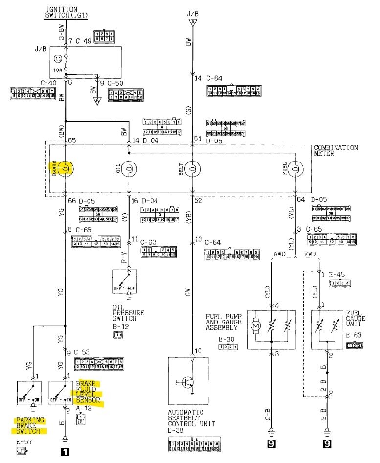
The Brake lamp on the dash is triggered in two possible ways, either there is low brake fluid in the master cylinder or the Parking brake switch is engaged (diagram 2).
Checking the voltage level for the idle position sensor with the AC on shouldnt cause any additional issues. Its because we have started testing things and moving wires around and even the ECM connectors might have lose pin issues.

If the throttle plates look ok, and there isnt any black carbon around the edges of the plate, then just put the intake air boot back on and put everything back together.

Are you able to press on the gas pedal when cranking the engine? That will allow more air into the engine if the ISC motor is not moving its full range. Thats all the ISC motor does, its just moves in and out to open a port that bypasses the throttle plate and allows air in to control the idle. And thats why its position voltage should increase as well with the AC on, because its opening more to up the idle.

Diagram 4 are the Power and Ground wires at the ECM.

Sorry for the delay, but I have found some more diagrams that link things together, I will post them next.
Was this
answer
helpful?
Yes
No
Wednesday, October 9th, 2024 AT 2:16 PM
Tiny
AL514
  • MECHANIC
  • 4,795 POSTS
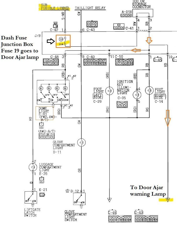
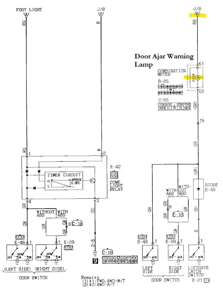
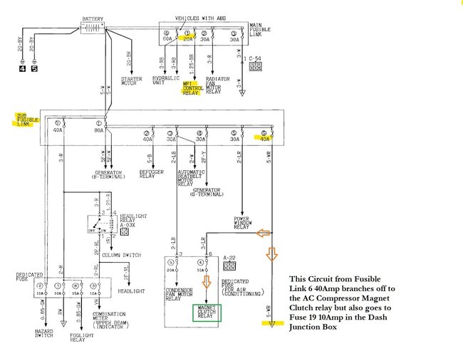
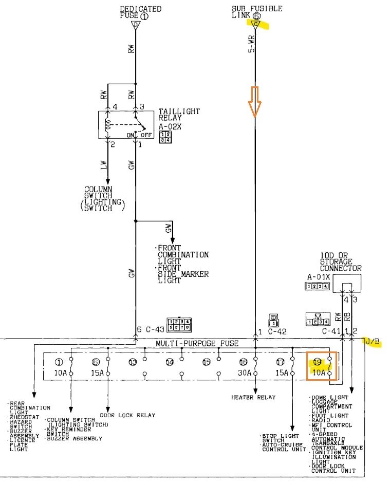
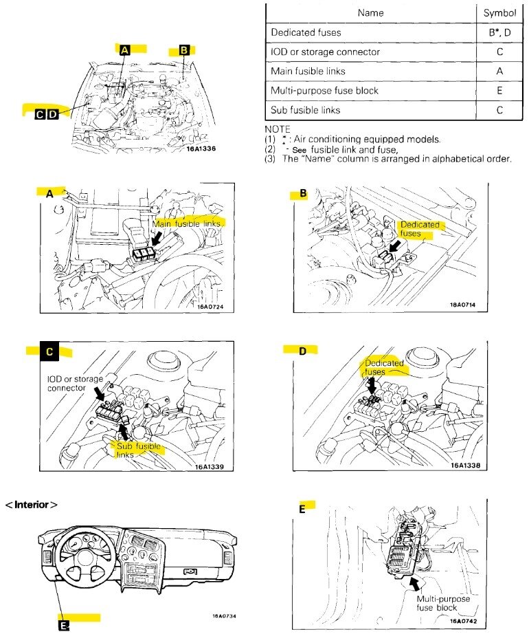
So, these two first diagrams are for the Door Ajar lamp which originates from Fuse 19 10Amp in the dash fuse junction box, but what is interesting is in diagram 3 notice that Fusible Link 6 40Amp branches off and goes to the AC Clutch Relay, then also goes to that same Fuse 19 10Amp in diagram 4. So you may find a blown fuse that happened when the either the AC compressor Clutch came on, or something is wrong with the Relay that controls the compressor clutch. It does link together.
Diagram 5 shows all the fuse box locations Since there are 3 locations in the engine compartment and then one under the drivers side dash.
So with a test light hooked to ground, you should have power on both sides of each fuse. And check the fuse locations for any corrosion inside the pins as well..

https://www.2carpros.com/articles/how-to-check-a-car-fuse

https://www.2carpros.com/articles/how-to-use-a-test-light-circuit-tester
Was this
answer
helpful?
Yes
No
Wednesday, October 9th, 2024 AT 2:26 PM
Tiny
CODYBTUCKER
  • MEMBER
  • 19 POSTS
Sorry, I did not get to looking at any of the fuses yet.
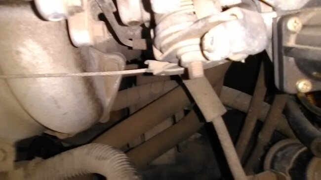
I'm not sure what constitutes carbon on the engine throttle plates because I didn't see any black, but when I ran my finger around the edges there was a blackish film on my fingers. The entire hose that goes from the volume air flow sensor to the throttle turns my hands black if I touch it. I unplugged the only connector I saw to the air conditioning clutch area; it was just a one wire connector (very difficult to get off)and it had a separate ground nearby. Did you tell me to replace the connector for the idle speed control motor position sensor, that was the one I sent you the photos of, but I do not know how to replace the connectors. I might need you to look at the distributor connector because I think it is worse because it fell off when I was trying to get the AC clutch connector off. I know this is a stupid question, but I need to know. You said to push the gas pedal when I try to start the car - does that mean I push the gas pedal before I turn the key, while I turn the key after I turn the key on All/any/some of the above or some other modification. The car still would not start today but it still cranks and has the instrument warning panel light confusions. I do not mean to leave things out but some things I forget to do or don't know how to do. I better send this before I fall asleep.
Was this
answer
helpful?
Yes
No
Thursday, October 10th, 2024 AT 10:24 PM
Tiny
AL514
  • MECHANIC
  • 4,795 POSTS
It's okay, I meant to push on the gas pedal while you are cranking to allow more air into the engine to help it start, the black stuff youre getting on your hands is carbon build up, if its all the way into the air intake boot, most likely its has contaminated the air volume sensor as well. But right now the harness connectors sound like they are in bad shape, they should not be falling off or loose in any way at all. That means you are probably not getting a crank or cam signal to the computer, both the ISC motor sensor and Distributor connectors need to be on solid and tight, or the pins inside the connector will not make any contact and nothing will happen. Cranking the engine over right now is pointless until you get those connectors repaired. If you are not familiar with wire repair or crimping new connectors on, it will take some time to explain it to you, send me pictures that I can clearly see both damaged connectors from the wire side as well as the inside pin side.
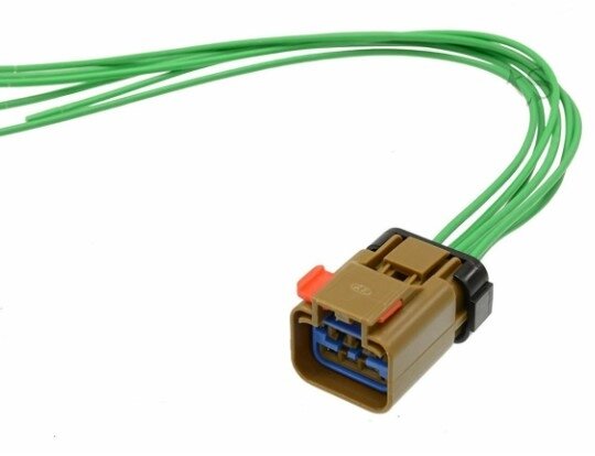
You can get new pigtails with a section of wires already connected to the pins but you will need to crimp the wires together in the correct places, and heat shrink them down to keep moisture out. I will explain all this, but see if you can even get new connectors for the Distributor and ISC motor position sensor. You may have to go to the dealership for this, I dont know, considering the age of the vehicle. But these repairs need to be done first.

Get a can of this electrical terminal cleaner, and these are heat shrink butt connectors, they crimp the wires together, and then you heat the ends and they will seal around the wires to protect from any corrosion. You can search you tube for any videos showing how to crimp wires together to get an idea of how it works.
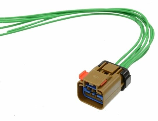
This is an example of a pigtail replacement connector.
Was this
answer
helpful?
Yes
No
Friday, October 11th, 2024 AT 9:27 AM
Tiny
CODYBTUCKER
  • MEMBER
  • 19 POSTS
Photos of the harness connectors. I think the distributor and the idle speed control motor position sensor connectors are the same.
Was this
answer
helpful?
Yes
No
Saturday, October 12th, 2024 AT 10:05 PM

Tiny
CODYBTUCKER
  • MEMBER
  • 19 POSTS
The two harness connectors are so heavily damaged that it is difficult to determine the shape, but I believe this is the part number.

MG640547-5 6 Pin Female MAF Sensor And Ignition Distributor For Mitsubishi

And I attached a link to a photo of the actual harness connector.

https://www.aliexpress.com/i/2251832663961130.html?gatewayAdapt=4itemAdapt

There's another one at the same link that has the pins already connected with the wires.
Was this
answer
helpful?
Yes
No
Sunday, October 13th, 2024 AT 4:30 AM
Tiny
AL514
  • MECHANIC
  • 4,795 POSTS
No you don't want to have to deal with re-pinning the connectors, you need to get a connector with a pigtail, so a connector with wires already pinned into the connector like I posted. (1st picture) this is the type of connector you need to get; it will take you forever to rebuild a connector with new pins, and then try to stripe the wires to fit those pins, then get them into the new connectors making sure they make perfect contact. It will never happen. You have to have a lot of experience even dealing with the pins to begin with. Don't buy any junk connectors from Amazon or some other cheap site, they are going to be incorrect like always, go to AutoZone or some local auto parts store and see if they can get you those connectors with pigtails already connected, and crimp the connectors together.

With a connector that already has the wires installed in it, you just need to go wire by wire one at a time and use crimp connectors (2nd pic) making sure you have the correct wire in the new connector going to the old wire from the old connector. Thats the only way you will be able to do this,
The other issue you are having is the low reference voltage. And most likely a ISC motor that has carbon build up inside, like I said, all the black soot that is in the air intake boot and around the throttle plates is carbon build up, your intake manifold is probably full of the same stuff. But that low reference voltage is definitely a problem, Pins 8 and 20 at the ECM should have a full 5 volts or those sensors will not read correctly. It looks like the ECM in the picture isn't even bolted down. I can only go so far with this, have you checked the power and grounds at the ECM yet? Your original post was for these four codes setting, the ECT is the first sensor the ECM is going to use during a cold start.
And the engine needs air which the ISC motor provides, in the 3rd diagram below is the code setting criteria, the 3rd row over are the voltage levels that will cause that code, the 4th row over are some possible causes, same with the other codes,

You may need to have a mobile technician come out and look at the vehicle, not some shop where they don't know what they are even looking at. It will save you a lot of time and a headache. Just have a mobile tech come out, tell him about the low reference voltage, and the codes, let him figure out what's wrong, it will probably take an hour of diagnostic time, then fix what's wrong yourself, there are too many issues with this vehicle and possibly a bad ECM to figure this out on your own, I know you want to, but it takes years to learn how to properly diagnose these things, if I could I would come to your house and help. But that's not possible unless you live in NC. I'm helping with the relief work from the flooding in Ashville NC too. Bouncing back and forth here. It would just help you so much at this point to pay a mobile guy for an hour or two of diag time, just to figure out the issues. Where are you located?
Was this
answer
helpful?
Yes
No
Sunday, October 13th, 2024 AT 9:26 AM
Tiny
CODYBTUCKER
  • MEMBER
  • 19 POSTS
I was hoping to remove the wires as they are in the connector and put them into the new connector since the connector is damaged and the wires probably are not - then I would not be stripping or connecting wires to wires.

Is it possible for me to determine if the car is getting fuel, spark, and Air while it turns over (I crank it by turning the key to the start position) to make sure that fuel, spark and Air are available for it to run?
I am in Daleville Alabama.

If someone could guarantee me that the car would run forever by guiding me through repairs and maybe even get the check engine light to go out, I would work with them, but I'm absolutely sure that that is not possible -working with anyone that charges money is catastrophic:
Kelley Blue Book shows the value of this car to be between $400 and $1,500, so I would be a fool to pay anyone to do anything since it may never run again and I might not even get $400 for it if it's not running - I might not even be able to donate it to a local used car dealer with a mechanic.
This car running is like a perfect and beautiful Ferrari to me, broken this car is like being stabbed in the back forever.
Mitsubishi does not even work on cars older than 2010, and they don't even know who makes the harnesses for the cars they sell now. There are hundreds if not thousands of functioning parts on this car that should be utilized until the parts have met a demise that is far greater than where this car and its parts currently are. The government should make every manufacturer of automobiles make sure that every car that is repairable is repaired or rebuilt if condition allows and to force manufacturers to focus on repairability and customer satisfaction.
Was this
answer
helpful?
Yes
No
Friday, October 18th, 2024 AT 3:55 AM

Please login or register to post a reply.

Sponsored links