Check Engine light on since 2013?

Tiny
CODYBTUCKER
  • MEMBER
  • 1993 MITSUBISHI ECLIPSE
  • 1.4L
  • 4 CYL
  • 2WD
  • MANUAL
  • 212,000 MILES
Codes:
13 intake air temp circuit.
15 motor position sensor out of range.
21 coolant temp sensor out of range.
23 baro pressure sensor circuit

Used to get about 36 miles to the gallon now I think it gets near 20 miles to the gallon, but I spend a lot of time working on it now so it sits at idle a lot.
Hard to start when it's cold, it takes about 10 ignition cycles for it to start if it's below 70° and overcast. If I push the car out in the sun and let it shine on the engine if it is above 50 degrees, it will normally start right up. Around 2013 when I used to use the air conditioner sometimes it would die out if I was at idle when turning on the air conditioner or it would struggle to run while idling with the AC on. Shortly after that the car quit running all together and I had to replace the computer (rebuilt computer) but the check engine light never went out since the 2013 computer replacement. The exhaust smells like its burning fuel poorly sometimes it's a little whitish other times it's blackish. I just replaced the distributor because I was told that's where the crank and camshaft sensors are and now the car makes a slight ticking sound when I accelerate under a load or I'm in a too high gear. I have never cleaned or replaced the catalytic converter, and the timing belt has about 64,000 miles on it. Four or five mechanic shops have worked on it and none of them have gotten the check engine light to go out or even mentioned what codes it has. I drove the car to one mechanic shop, and he kept the car for 4 years and 4 months and I had to replace the idle air control valve and jump it off to take it to another mechanic shop and the fuel gauge was broken when I recovered the car. The next car repair shop replaced the fuel pump in the fuel tank spark plugs and the battery but did not repair the check engine light or the starting problem. Now I think I have a battery problem as well because I'm able to charge the battery and start the car when the battery is cold, but when the car gets hot the battery will not start the car but I'm able to jump it off to start the car, and I monitor the voltage while the car was running to see that the alternator is charging the battery at about 14.2 volts. As the car was getting hotter the voltage was slowly going down around 13.8 and when I turn the car off it would not start without an external power source.
Thursday, September 19th, 2024 AT 10:23 PM
44 Replies

Tiny
AL514
  • MECHANIC
  • 4,795 POSTS
Hello, so for this year being its age, the service information wiring diagrams are not very helpful, but with all these sensors alone setting codes, the Intake air temp sensor (IAT), Coolant temp sensor (ECT), and the Barometric pressure sensor most likely all share the same 5 volt reference voltage regulator inside the ECM. When it comes to thermistor's which is what the IAT sensor and ECT sensor are, to check the 5-volt feed, the sensor needs to be unplugged to check for a full 5-volt feed. Key On, Engine Off, one of the two wires to the sensor should read 5-volts, if for some reason that 5-volt feed is shorted out, whether its inside the ECM or another sensor causing it, it will cause those sensors not to read as an input to the ECM.

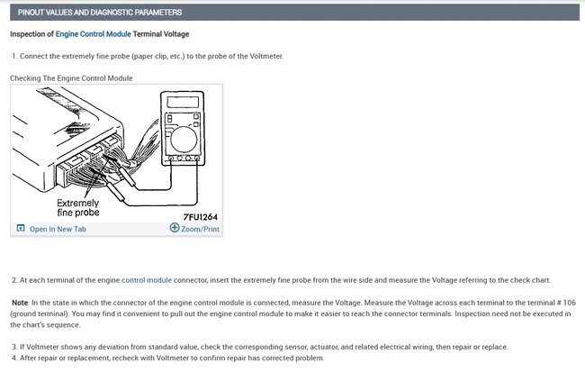
Service info does provide the pinout for the ECM connector which, after you check at the sensors for its 5-volt, if something doesn't look right, you would check it at the ECM. It sounds like the "new" ECM you installed, being a remanufactured computer, might have come with problems, many rebuilds do. But this is a very basic setup except that you can't get the best live engine data on a scan tool being that this is an OBD1 system, newer systems from 1996 and newer are all OBD2 with advanced scan tool options.
I would start by checking the IAT sensor unplugged, if 5 volts is there, plug it back in and check the ECT unplugged, I say thing because if either the IAT is shorted out the 5 volts, or the ECT is shorted out, you won't know when checking the next sensor if the previous sensor is still unplugged during testing, if that makes sense.
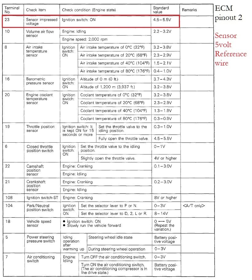
I see in the ECM pinout diagram there is only 1 sensor 5volt reference feed for them all, so that's something to check.

I would also do a voltage drop test on the ECM grounds. If this computer has a temperature related issue, such as a cracked solder joint inside, you will end up with thermal type issues like this. And unfortunately checking at the ECM connector will not tell you if there's a cracked solder joint on the circuit board.
But in some cases, a bad ECM ground can cause the 5volt reference to rise to a higher voltage, bad grounds can cause all kinds of very difficult issues, especially when they are internal to the ECM itself.
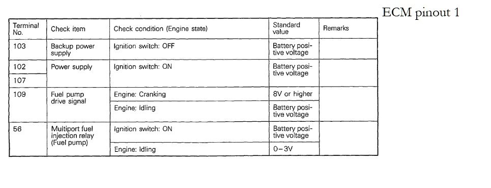
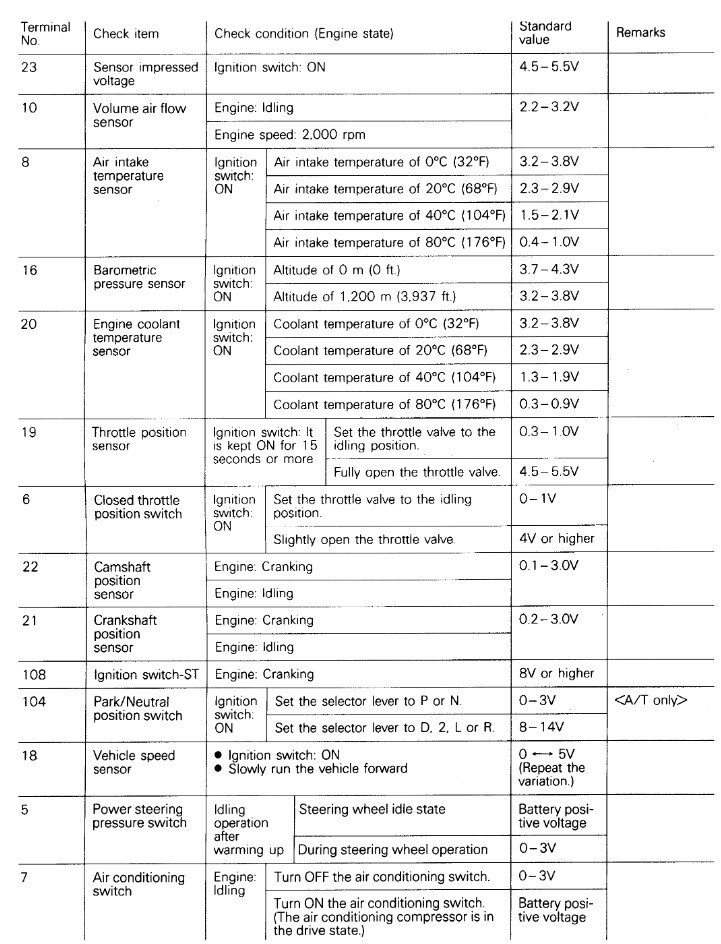
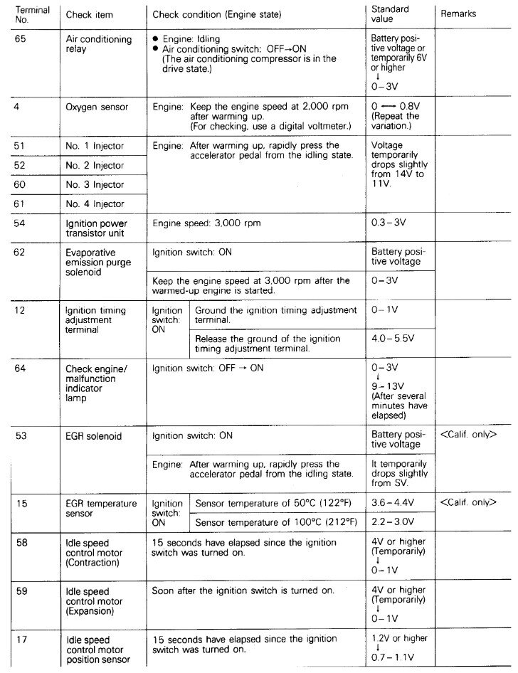
But I will post the ECM pinout for its connector so you can check the voltage readings at it if necessary.

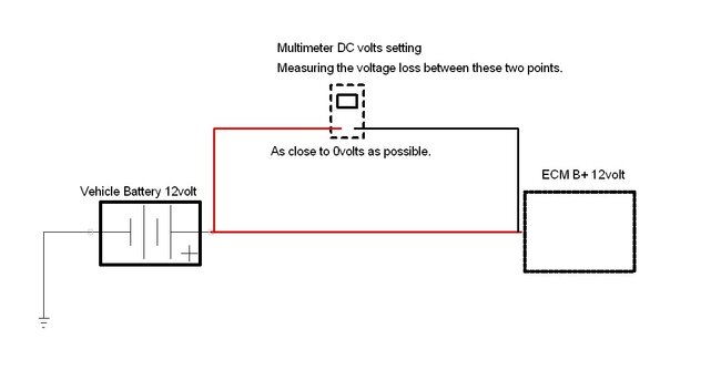
To do a voltage drop test, for example you are measuring from Positive to Positive, so if checking for voltage drop from the Battery + to the ECM B+ feed, you would have a meter set to DC volts and check from Battery + (positive) to the wire that feeds the ECM B+ and with the vehicle running it should be as close to 0volts as possible, there will be a little bit but it shouldn't be over 0.5volt at its extreme max, so when the vehicle is hot and some electrical loads are on such as headlights, etc.

https://www.2carpros.com/articles/how-to-use-a-voltmeter

https://www.2carpros.com/articles/how-to-use-a-test-light-circuit-tester

https://www.2carpros.com/articles/everything-goes-dead-when-engine-is-cranked
Was this
answer
helpful?
Yes
No
+1
Friday, September 20th, 2024 AT 2:16 PM
Tiny
AL514
  • MECHANIC
  • 4,795 POSTS
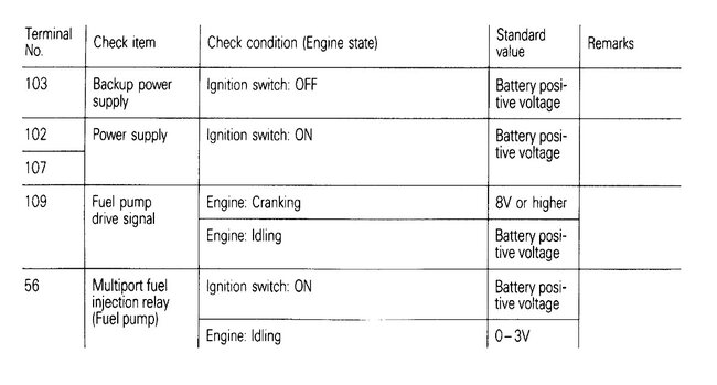
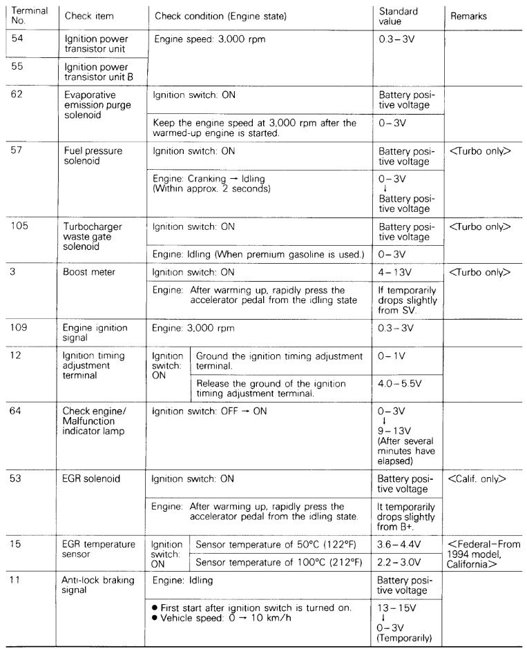
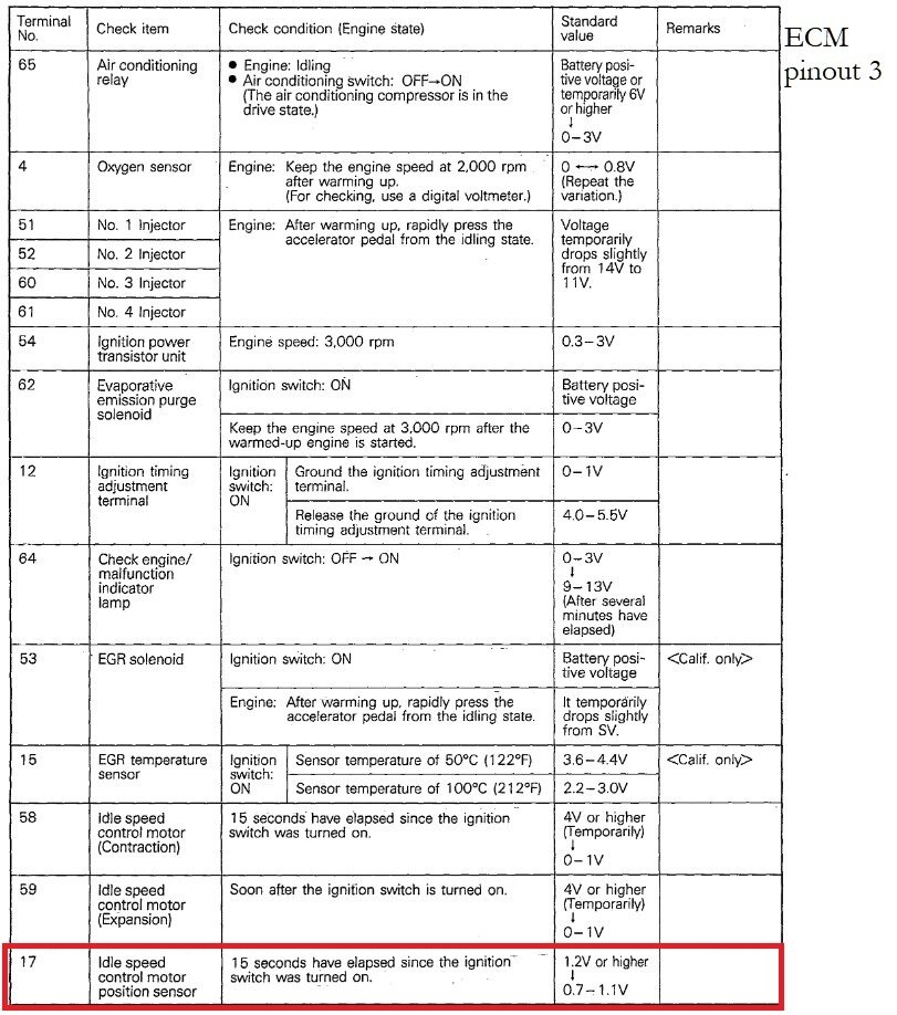
These are the ECM connector pinouts, there are additional voltage values for each pin I will post next, since this doesn't seem to list all pins.
Was this
answer
helpful?
Yes
No
+1
Friday, September 20th, 2024 AT 2:34 PM
Tiny
AL514
  • MECHANIC
  • 4,795 POSTS
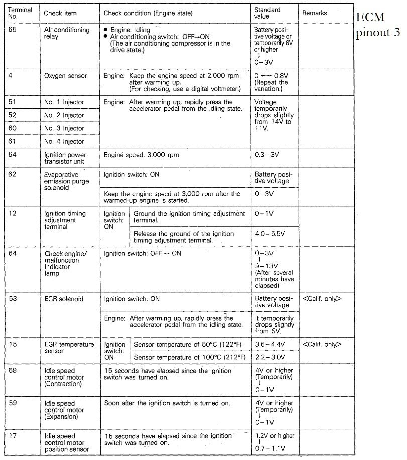
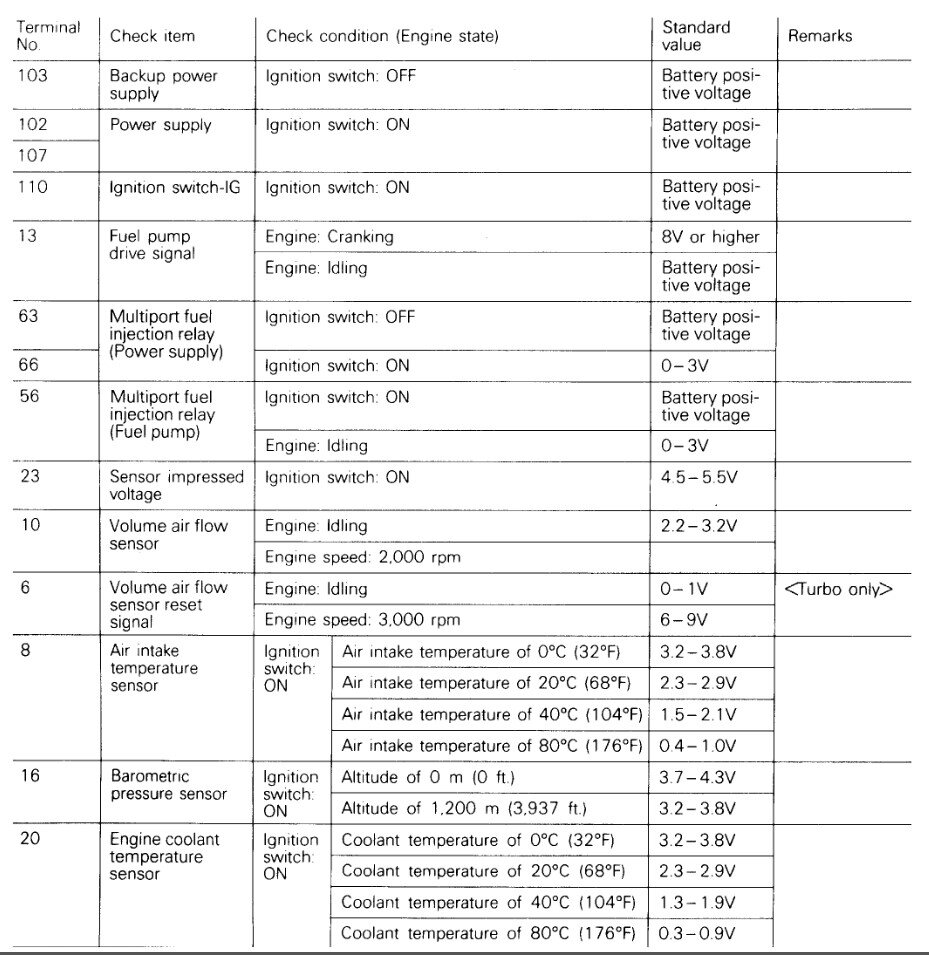
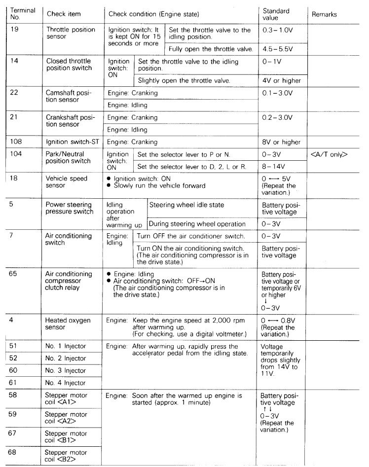
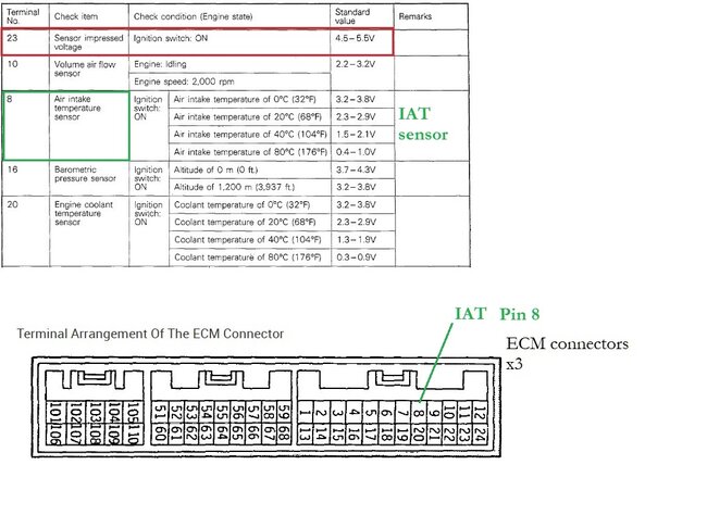
These are the voltage values you should read with the key on, and then engine running.
Was this
answer
helpful?
Yes
No
+1
Friday, September 20th, 2024 AT 2:36 PM
Tiny
AL514
  • MECHANIC
  • 4,795 POSTS
This is a simplified voltage drop testing diagram, excuse my artwork.
Was this
answer
helpful?
Yes
No
+1
Friday, September 20th, 2024 AT 2:48 PM
Tiny
CODYBTUCKER
  • MEMBER
  • 19 POSTS
Do you have the diagrams to show me accurately where the intake air temperature sensor is engine coolant temperature sensor and the barometric pressure sensor and if there's an engine position sensor, where it is located. I know those are basic knowledge for someone like you, but that's not the case with me.
Was this
answer
helpful?
Yes
No
Saturday, September 21st, 2024 AT 10:14 PM
Tiny
AL514
  • MECHANIC
  • 4,795 POSTS
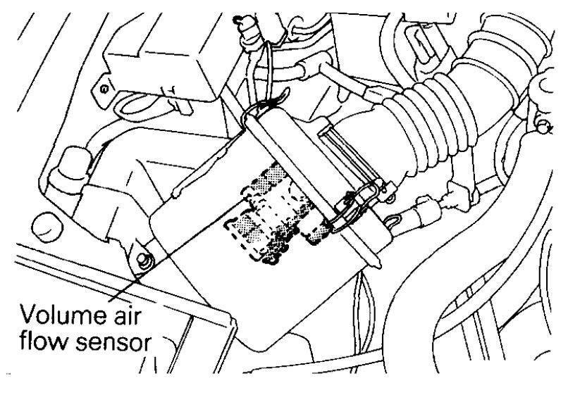
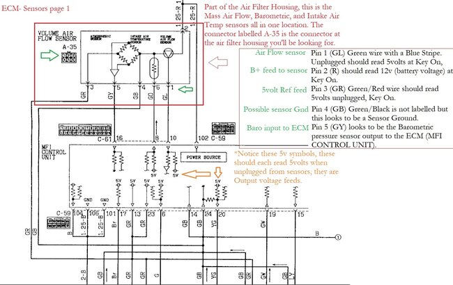
The wiring diagrams for this year are very difficult to read and were hidden on the transmission wiring diagrams, but the Intake Air Temp sensor and the Barometric Pressure sensor are built into the Mass Air Flow sensor which is part of the air filter housing, so you should see a 5 or 6 wire connector going to it.
Sorry for the delay, hopefully these diagrams are easily understood, if you have any questions on testing, just ask, It sounds like a part of the Mass air flow sensor (volume air flow sensor) may have stopped working, or there may be some corroded connectors in between the sensors and the ECM (engine computer). Since it's only these 4 sensors setting codes and not others. There are other sensors that work off the 5volt reference that appear to not be setting any codes, such as the Mass air flow sensor, but other sensors built into that one component are setting codes, so it can be tricky.
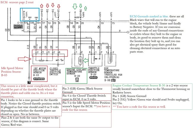
I would start by verifying the 5volt feeds wires to the sensor in the air box, at its connector. I've tried to add as many details as possible to the wiring diagrams, but I know this testing can be difficult if you're not familiar with it.
When checking for any of these 5volt feeds, use Battery negative as your meter ground (black lead) and the red lead for reading the voltage levels with the Key On, engine off to begin with. I will try to locate the Coolant temperature sensor as well.

https://www.2carpros.com/articles/how-to-use-a-voltmeter
Was this
answer
helpful?
Yes
No
+1
Sunday, September 22nd, 2024 AT 2:27 PM
Tiny
AL514
  • MECHANIC
  • 4,795 POSTS
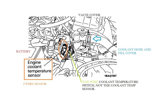
Here is the location for the coolant temperature sensor, there looks to be another temperature switch by it that is probably just a one wire temperature switch and not the sensor setting the code.
Was this
answer
helpful?
Yes
No
+1
Sunday, September 22nd, 2024 AT 2:37 PM
Tiny
CODYBTUCKER
  • MEMBER
  • 19 POSTS
Idle speed motor position sensor pin voltage readings:
1 has no wire - you said it might be a case ground.
2 (GR wire) 5.0 volts.
3 (GB wire) 0 volts.
4 (G wire) 11.3 volts.
5 (Br wire) 0 volts.
6 (GR wire) 5.0 volts.
Pins 4&5 might be a problem as you said pin 4 should read either 0 or 5 volts and pin 5 should be the voltage to the ECM (computer).

DROP TEST RESULTS:.7 volts

ECM voltage readings- temp 83° 250' pressure altitude key on:
Pin 8 - volts 1.1 IATS
Pin 16 - volts 2.3 barometric pressure sensor
Pin 20 - volts 1.1 ECTS
Pin 19 - volts.3 throttle at idle volts 2.9 throttle full open - throttle position sensor.

Engine running voltage readings:
Pin 8 - volts 1.7
Pin 16 - volts 3.3
Pin 20 - volts.4
Pin 19 - volts.5
Pin 10 - volts 2.5 idle and at 2000rpm was same - VAFS volume air flow sensor.

The air intake temperature sensor, barometric pressure sensor and engine coolant temperature sensor all seem to be off with the key on engine not running per the parameters listed with the pinout diagrams.

I'm still having trouble understanding all the variations in the components involved in the engine, electronics and components or accessories of the car, so please be patient and allow errors on my part.

I read 9.3 volts on the 1 wire sensor beside the 2 wire engine coolant temperature sensor because I was curious what it was and it had volts.

Thank you very much for helping!
Was this
answer
helpful?
Yes
No
Sunday, September 29th, 2024 AT 1:25 PM
Tiny
CODYBTUCKER
  • MEMBER
  • 19 POSTS
I sent these voltage readings from the six pin connector at the MASS AIR FLOW SENSOR a few days ago but I didn't see the post on your site:
IATS Pin 1 (GL wire) 4.5 volts.
Pin 2 (Red wire) 12.5 or battery volts.
Pin 3 (GR wire) 5.0 volts.
Pin 4 (GB wire) 0 volts.
Pin 5 (GY wire) 0 volts.
Pin 6 (GY wire) 3.9 volts -barometric pressure sensor.

Engine coolant temperature sensor with two wires:
Yellow with green stripe - 3.9 volts
Volts 0 (GB wire).

I didn't see any ground connectors to the car that had corrosion in my opinion.

Thank you for helping.
Was this
answer
helpful?
Yes
No
Sunday, September 29th, 2024 AT 1:47 PM
Tiny
AL514
  • MECHANIC
  • 4,795 POSTS
Hello, I'm sorry for the delay, I am in North Carolina just east of where the storm hit and we're sending supplies to people we know in Asheville, I do apologize for not getting back to you sooner.
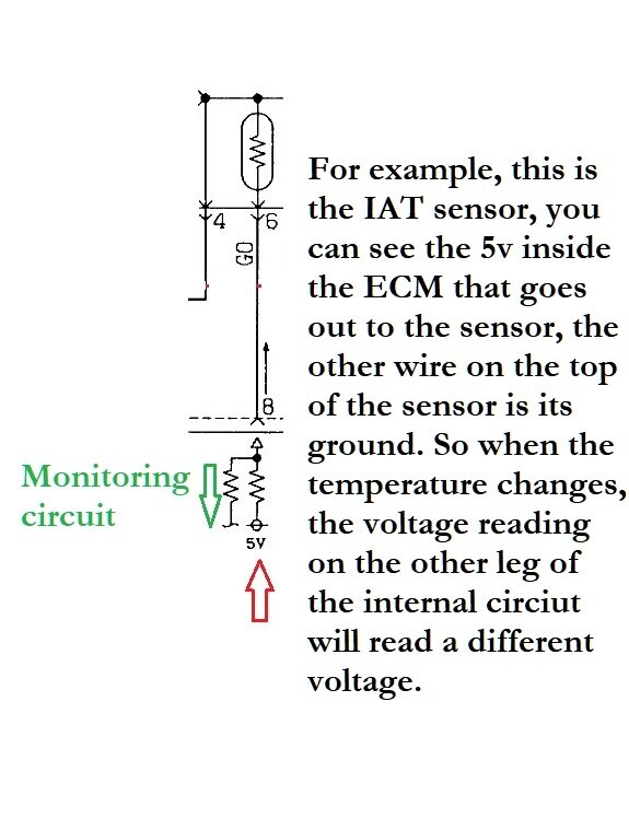
It does look like some of those readings are off, I will have to pull up the file on your vehicle again and review the diagram again, but with thermistor components such as the IAT and ECT, the ECM sends out 5-volts to the sensor and the ECM monitors that 5volts internally for any change in voltage. And because the thermistor is basically a resistor that changes resistance with temperature fluctuations, higher or lower temperatures will cause the sensor to vary the voltage the ECM is seeing on the monitoring circuit through a resistor. The resistor helps also if the 5volt ref happens to be shorted to ground. It's a protection device. Let me look over your testing results really quick.
Was this
answer
helpful?
Yes
No
+1
Monday, September 30th, 2024 AT 12:17 PM
Tiny
AL514
  • MECHANIC
  • 4,795 POSTS
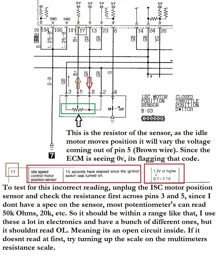
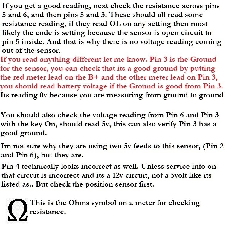
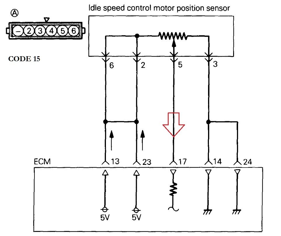
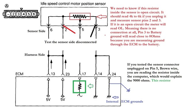
Okay, so on the idle speed motor, pin 5 is the motor's position signal wire, it should not be just 0 volts, you notice how it is in between pin 3 and pin 6, here's some resistance checks to do on the position sensor. You're missing the motor's position signal to the ECM.
Was this
answer
helpful?
Yes
No
+1
Monday, September 30th, 2024 AT 1:16 PM
Tiny
AL514
  • MECHANIC
  • 4,795 POSTS
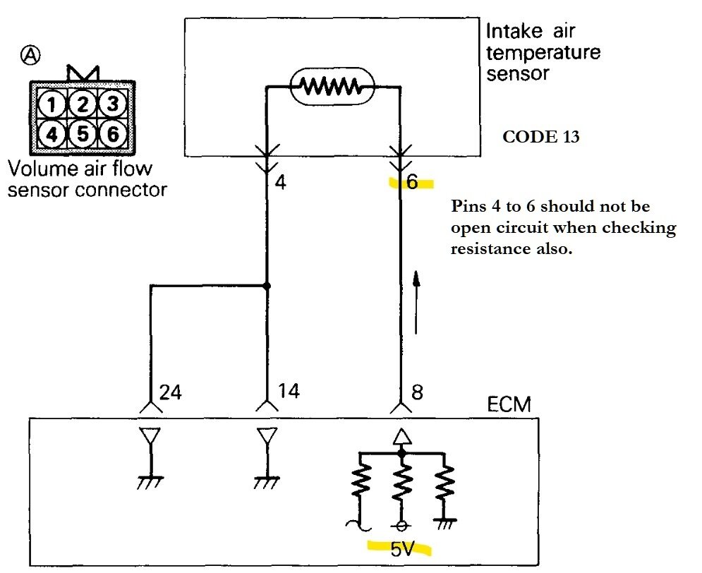
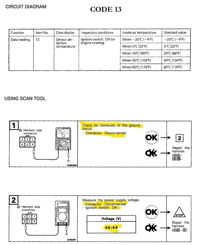
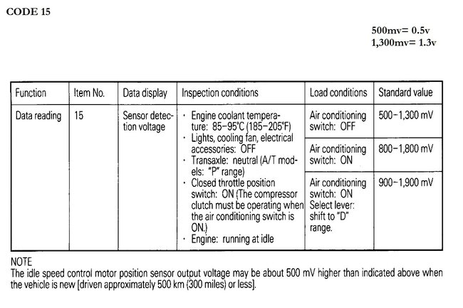
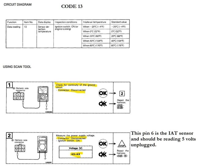
This is additional testing for Code 13, I'm going to post these, because I'm seeing some service info that varies a lot.
Was this
answer
helpful?
Yes
No
+1
Monday, September 30th, 2024 AT 2:03 PM
Tiny
AL514
  • MECHANIC
  • 4,795 POSTS
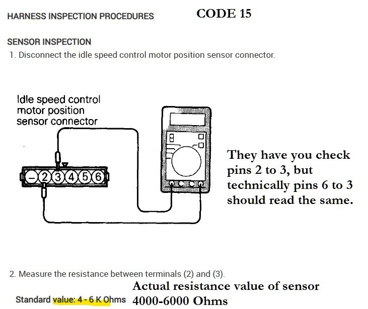
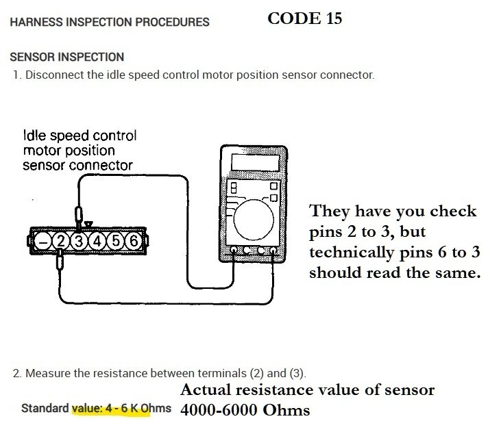
This is for Code 15, the ISC motor position sensor's resistance value is actually only 4000-6000 Ohms.
Was this
answer
helpful?
Yes
No
+1
Monday, September 30th, 2024 AT 2:04 PM
Tiny
AL514
  • MECHANIC
  • 4,795 POSTS
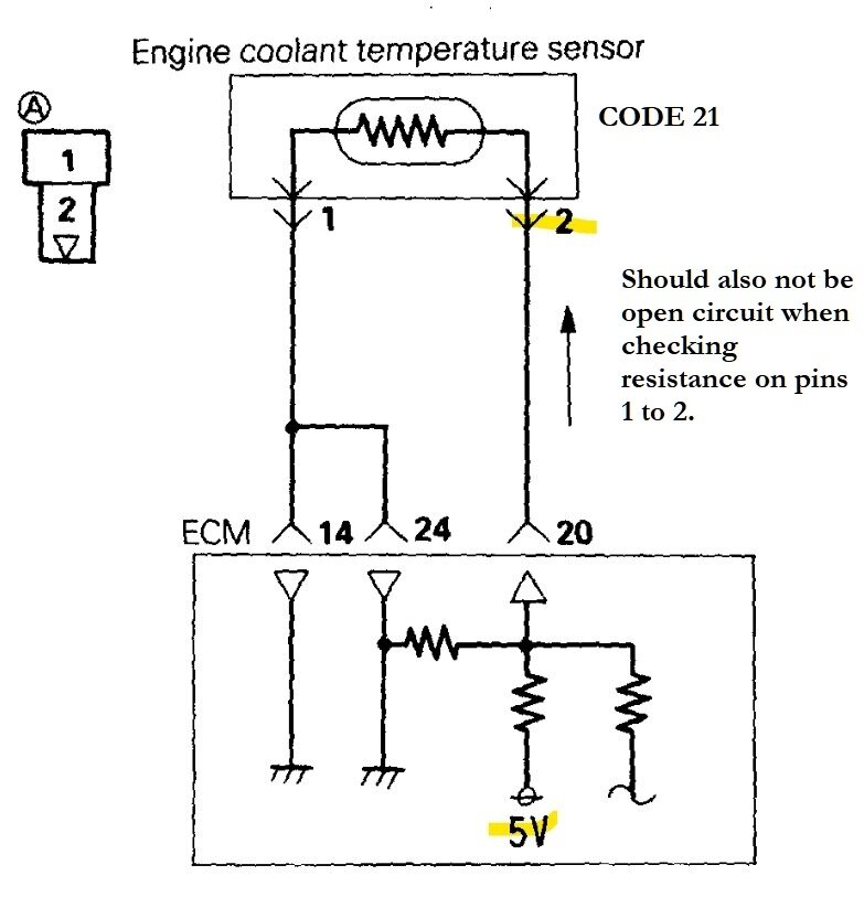
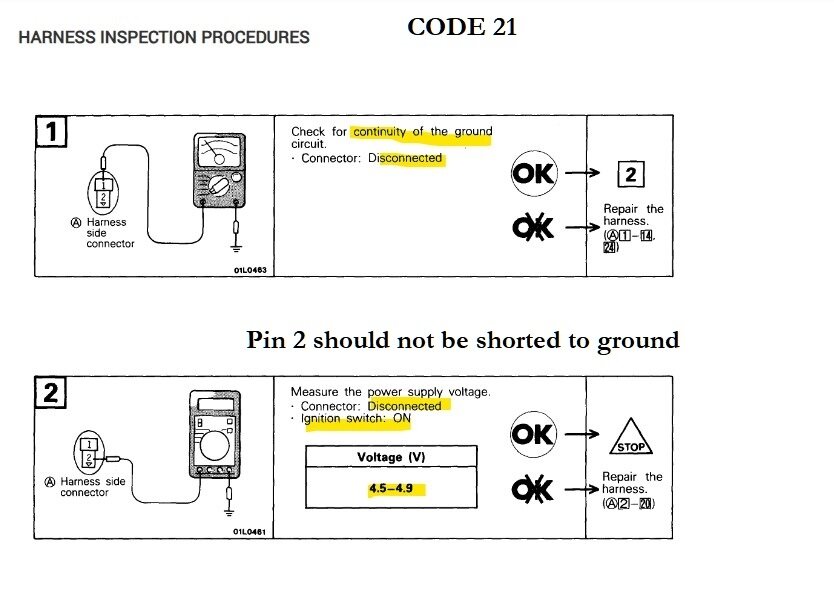
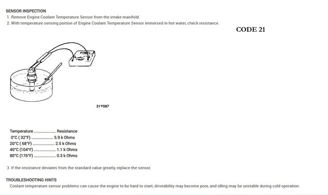
This is Code 21 ECT.
Was this
answer
helpful?
Yes
No
+1
Monday, September 30th, 2024 AT 2:05 PM
Tiny
AL514
  • MECHANIC
  • 4,795 POSTS
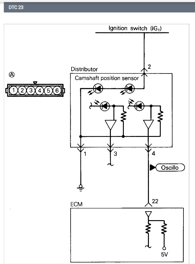
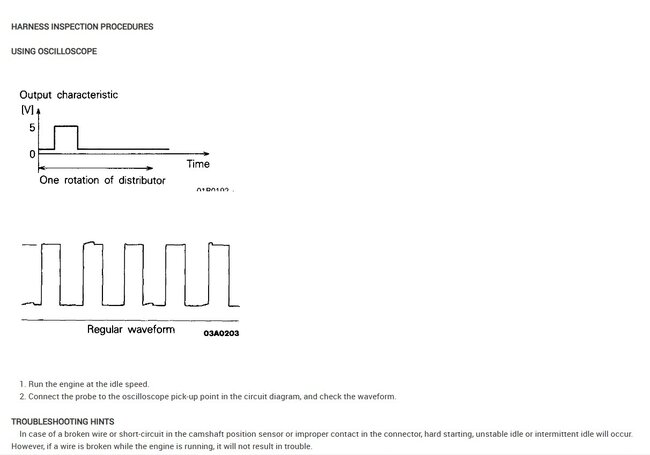
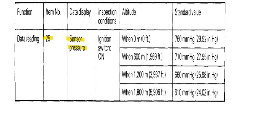
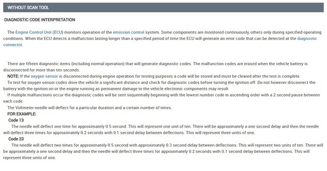
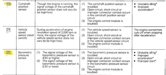
But Code 23 in service info is not listed as Baro sensor, it is stating a camshaft position fault. The Barometric pressure sensor fault is listed as Code 25 (diagram 3). I don't know if that was a scan tool reading the code incorrectly, the camshaft and crankshaft position sensors are inside the Distributor on this vehicle, and if they were not functioning, you would have a crank no start condition.
Was this
answer
helpful?
Yes
No
+1
Monday, September 30th, 2024 AT 2:14 PM
Tiny
CODYBTUCKER
  • MEMBER
  • 19 POSTS
My ohms selection of Rx1k and Rx10 reads exactly the same, so I am giving these values as if it is R1k.
Idle speed motor position sensor:
PIN 2 GR = 0
PIN 3 GB = 0 tested to battery
PIN 4 G = 2000
PIN 5 Br =9000
PIN 6 GR = 0

Volume air flow sensor:
The PIN numbers and the color of wires do not match up per the A35 connector on the diagram you attached.
GL = 800 ohms
R wire = 1200
GR = 0
GB = 0 to the battery gnd.
GY = 9000
GO = 1600

Coolant temperature sensor:
YG wire= 1600
GB = 0 to battery

Notice the GO and YG wires have the same ohms and they both had 3.9 volts, and I think they both are supposed to have 4.5 to 4.9 per the maintenance charts you attached and the charts say to repair the harness.

I installed a new distributor and it performed just like the one that I had in there, so I put my old one back in and I'm going to send the new one back because I don't need a bunch of spare parts if I never get this car to run right. I will rule out the cam and crankshaft sensors because of that distributor and I also checked the volts at the engine control module and they seemed to meet the variables on the chart.
Was this
answer
helpful?
Yes
No
Tuesday, October 1st, 2024 AT 11:01 PM
Tiny
AL514
  • MECHANIC
  • 4,795 POSTS
I'm not surprised if some of the wire colors are not correct, this is very old service information. I'm going to post this info first, but I'm looking over your readings you took at the ECM again, it states 83f degrees out, but the IAT sensor is at 1.1v and the ECT is the same These are Key On engine Off readings I assume,

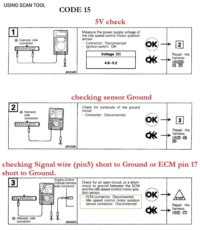
But the Pin 19 is the Throttle Position sensor that's the incorrect sensor, we need ECM Pin 17 that is the Idle Speed motor position. If Pin 17 at the ECM is reading 0volts like it is at the idle speed motor, that's why the code is setting.

Some of these wire colors will fade over the years and it can be difficult to tell what color they are. So for A-35 we will have to go with wire/pin location in the connector.
It might also be that, when disconnected they are showing the connector face (so the wiring harness side of the sensor's circuit), looking at the female pins of the connector.

While checking the Idle Speed Control motor position sensor (diagram 1 below) you didn'tt have 4000-6000 Ohms (4k-6k) across pins 2 and 3?
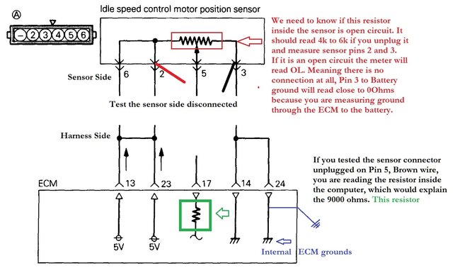
We just need to know if the sensor is open circuit inside (diagram 2). I think you were testing the harness side of the circuit, when unplugging it, check the male pins inside the sensor side, not the harness side.

We need to check each sensor that is setting a code for an open circuit internally first, If that reads ok, then we move on.
So its the same with the coolant temperature sensor, unplug the two wire connector, move it aside and measure the sensors male pins. Sorry I know these wiring diagrams are not the best by any means.

Thats why in the 3rd diagram when checking pin 3 you had 0 ohms because its the sensors ground wire. But since these diagrams are so old, we would load test wires these days and only use continuity testing to see if there was a short to ground.
The low voltage is a concern though, diagram 4 and 5 are for the IAT 5v reference at the sensor connector(unplugged) and then the ECM connector(plugged in still) back probed.

Those low voltages will cause incorrect readings, and starting issues if the ECT has low voltage because the coolant temp sensor is the main sensor the ECM looks at during a cold start.
Was this
answer
helpful?
Yes
No
+1
Wednesday, October 2nd, 2024 AT 2:46 PM
Tiny
AL514
  • MECHANIC
  • 4,795 POSTS
This is the code setting criteria for Code 13 IAT. With the engine running, readings at ECM pin 8 at 1.7volts looks normal, or within range around 104f degrees, which is okay.

The next is Code 21 ECT, running at 0.4volts is around 180f degrees, which looks normal too,
So, this might be an intermittent issue with this ECM, obviously you're getting some lower-than-normal 5v reference readings. But Pin 17 needs to be checked to verify this code 15 ISC motor position,
But I would recheck the pin 8 and pin 20 with both the IAT and ECT sensors unplugged at the same time and see if the full 5volts comes back,

The Code 23, we will have to check last, because it's listed as Cam sensor,
But you can see the code setting criteria in the diagrams 1 and 2 below, it's possible the ECM circuit board may be having an issue either when hot or cold. And that's when these codes are setting, these older ECMs are also pretty easy to repair if this is a soldering or corrosion issue on the circuit board. I've repaired them in the past, due to broken solder traces and such.

The 11.4volts on Pin 4 of the ISC motor position sensor is incorrect unless service info is wrong on what voltage is supposed to be on that wire, because it's the position sensor setting the code, and we need to know if that is open circuit or not inside the sensor, if Pin 5 was checked with the sensor unplugged you would read nothing, we need to resistance value on pins 2 and 3. I'll post that again (diagram 5).
Was this
answer
helpful?
Yes
No
+1
Wednesday, October 2nd, 2024 AT 3:13 PM
Tiny
CODYBTUCKER
  • MEMBER
  • 19 POSTS
You are correct; all of my readings were from the harness or the female side (sorry) it never occurred to me to check the sensor. I assume the redo readings for pin 8 and 20 in the engine control module with the idle speed control motor position connector and the engine coolant temperature connectors disconnected are with the key on but not idling the engine - I know that sounds like a stupid question, but you deserve a lot better than you're getting from me because if it can be screwed up - I'll screw it up.
I do have on my code list from 2013 the camshaft sensor and the mass air flow sensor but they didn't have a number written by them, so there was probably some confusion. This reading was done in 2013 and there were several people helping me or doing it for me actually. I tried to have the codes read again last week as they do have the correct connection, but the device said something like failure to communicate or connect.
I did not tell you that the car turns off when it gets hot because a mechanic told me that the problem was caused by low coolant, but I don't know how that turns the car off and makes it not start until it cools off for an hour and the temperature needle never goes up on the instrument panel. I also had driven the car until the instrument panel needle was in the red (hot and it never shut down) one summer trying to get to a water hose after the belt broke that turned off the water pump and some other things. I noticed the new replacement distributor would not shut the car down like my original distributor when it got hot, but the new replacement distributor wouldn't start when it was hot (might be a battery with a temperature problem or short), and the original distributor was the one that shut down when it gets hot and now that I put the original distributor back in - the car shut down again today when it got hot. But the original distributor will still start once it cools down - I think it takes a little over an hour for it to cool down and start again. There is damage to the coating or framing of the plug connection of both the six pin distributor connection and the six pin idle speed control motor position sensor connector. It might take me a few days to try to make sense of what I have to do, but I will be working on it.
Was this
answer
helpful?
Yes
No
Wednesday, October 2nd, 2024 AT 9:53 PM
Tiny
AL514
  • MECHANIC
  • 4,795 POSTS
Well, don't be too hard on yourself, the crank sensor and cam sensor are inside the Distributor, along with the ignition coil and a power transistor that triggers the coil on and off. A common symptom of a bad crank or cam sensor is a hot or cold stalling issue, more on the hot side like you are experiencing, when the sensor gets hot, it expands and if there is a wire (winding) in the crank or cam sensor that is touching when it's cold, it will open up when hot, and there's your stalling issue. It will cool down and start to function again.
I would clear the codes out completely and see what ones come back now, since it's been so many years.

As for checking Pin 8 and 20 at the ECM, Pin 8 is the Intake Air Temp sensor, Pin 20 is the ECTemp sensor. I would unplug them both at the sensor, then key On, engine Off, see if the full 5 volts comes back on both wires,

There might be more than one 5-volt regulator inside the ECM, it's unlikely on an old computer like this, but who knows.

Now depending on how bad the damage is to the connector of the idle motor sensor, if there are wires that are shorting together, meaning the pins inside the connector are touching in any way, that might be the issue for all these problems, the damaged connector is most likely going to be the cause of the Code 15.

I'll explain; if this ECM has just one 5-volt supply internally that it uses for all the sensors in the vehicle, and if the idle motor position sensor connector is shorting out the 5-volts to ground or to another wire that's pulling it low, such as the lower voltage you were reading, that is going to affect multiple sensors, and if it is an intermittent issue where the wire is shorting out, then it's not, then it is, you can see the turmoil that will cause.

Pin 23 and 13 of the ECM are supposed to be a 5volt reference for the sensors, you can see it in the diagram that goes to the idle motor position sensor.
It might not be the Distributor that's getting hot and causing the stall though, if the new one has the same symptoms, it might be the ECM getting hot and shutting down the vehicle.

When it shuts down when hot, turn the key On and see if the Check Engine light comes on for a few seconds, if it doesn't that indicates the ECM is probably not powering up, also check the 5volt Ref when its stalls out hot, Pin 23. I'll bet it will be missing or low voltage.

A bad ECM is difficult to diagnose. Sorry, this is all so complicated, it's because we are dealing with multiple codes, but erase them if possible and see what comes back, if you don't have a scan tool you can ***disconnect the battery for at least 10 seconds should clear the codes.

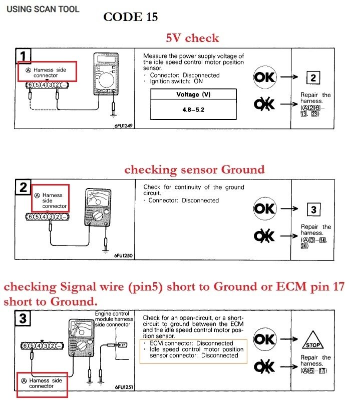
Reading codes on this system you will need a scan tool with an OBD1 adapter to it. (3rd diagram shows how they want you to read codes without a scan tool which requires an Analog multimeter, which I don't even know where you would get one that old anymore.)

Can you take a picture of the connector for the idle motor sensor so I can see the damage to it?
Was this
answer
helpful?
Yes
No
+1
Thursday, October 3rd, 2024 AT 5:33 PM

Please login or register to post a reply.

Sponsored links