Charging issue

2007 PONTIAC G6
165,000 MILES • 3.5L • V6 • 2WD • AUTOMATIC
Avatar
COLT THOMPSON
  • MEMBER
  • 2 POSTS
I have replaced the starter the battery and the alternator plus the fusible link on the wire running from the starter to the alternator. But the car still will not charge it just starts and runs and drains the battery.
Feb 20, 2018 at 6:32 PM
Advertisement
Avatar
CARADIODOC
  • CERTIFIED EXPERT
  • 34,308 POSTS
GM went from, in my opinion, the world's second best generator to by far the worst pile starting with the 1987 model year. The failure rate is very high, but that still did not satisfy the engineers. Now they added two not-so-reliable computers to the charging system. System information is calculated by the instrument cluster, then that data is transmitted to the engine computer. The engine computer controls the generator.

I do not have any information on this system's operation, but if the generator works as the diagram suggests, you can try taking some readings on the two smaller wires plugged into the generator. The orange wire is the turn-on signal that tells the voltage regulator to start running the generator. In the past, you would find about two volts on that wire with the ignition switch on and the engine not running. The other ten volts was dropped across the "battery" light on the dash, so that light was on. Once the engine is started and the generator is producing output, the regulator puts fourteen volts back out on that wire to turn the "battery" light off. If you find zero volts on that wire, suspect the engine computer or a break in that wire.

The gray wire is a duty-cycled feed for the generator's field winding. In the past that just had full battery voltage applied to it all the time. It is where the voltage regulator sensed system voltage and it was the supply for the field winding. There is no description to indicate how much this signal affects the generator's performance. To add to the misery, being a duty-cycle signal, it is a stream of voltage pulses that vary between zero and some maximum voltage, typically twelve volts, so it cannot be measured with a digital voltmeter.
Feb 20, 2018 at 7:46 PM
Avatar
COLT THOMPSON
  • MEMBER
  • 2 POSTS
Well thanks. I will look at those two wires on the plug and I will get back to you.
Feb 21, 2018 at 12:04 PM
Advertisement
Avatar
STEVE W.
  • CERTIFIED EXPERT
  • 15,116 POSTS
To add to what Doc posted. This is the charging circuit. Because of the way it operates you really need a scope to tell if the charge signal is getting to the alternator from the computer. The OEM tests use a scan tool, battery load tester and the charts below.

A shortcut I use to find if the problem is wiring or ECM is to remove the ECM connector and test the wiring from it to the alternator with a continuity tester, While it is on the circuit I will go along the harness and move the wires/connectors just to be sure there are no breaks.
If the wires are good and you have tested the alternator for actual output then the issue is likely in the ECM itself.
Feb 23, 2018 at 4:52 PM
Avatar
JAYJAY3
  • MEMBER
  • 24 POSTS
Hi, I have the same / very similar anyway, problem with an early 2008 G6 charging system. It stops charging at will. It charges till it the engine warms a bit, at 14.6V, then very intermittently. It also charges about the first 5 seconds of a ( hot engine) restart. Both the orange and grey wires have continuity, and pass an electrical load test. The battery and alternator and ECM are new. The positive and negative cables voltage drop test is in spec. Can you tell me more about how the meter is involved in this system?
Mar 6, 2020 at 4:51 AM
Avatar
ASEMASTER6371
  • CERTIFIED EXPERT
  • 52,796 POSTS
Good morning,

The ECM turning the alternator on and off is normal. That is why the ECM is involved. It will only charge when a load is detected or the battery voltage drops below 12.5 volts.

What is the issue that you have that makes you think you have an issue?

Roy
Mar 6, 2020 at 5:52 AM
Avatar
JAYJAY3
  • MEMBER
  • 24 POSTS
The car either charges at 14.6v, or not at all, until the battery dies while driving. I see a steady decline of system voltage while driving monitoring via accessory port plug in volt meter. it declines to about 10.4 then the car shuts off. Occasionally the voltage will jump to about 12.0 - 12.2v from 11.4- 11.7. That is on the highway with loads off.
Mar 6, 2020 at 9:23 AM
Avatar
ASEMASTER6371
  • CERTIFIED EXPERT
  • 52,796 POSTS
Okay, the engine will not run without 12 volts to keep the modules active. The alternator will not function either without battery voltage above 12 volts.

Do you have a scan tool that can turn the charging system on and off?

Roy
Mar 6, 2020 at 9:26 AM
Avatar
JAYJAY3
  • MEMBER
  • 24 POSTS
It acts like something overrides the ability to turn on. I do have 2.9v on the wire to the alternator, koef also.
Mar 6, 2020 at 9:43 AM
Avatar
JAYJAY3
  • MEMBER
  • 24 POSTS
Roy,
I do. and on or off when it acts up I get no charging operation.
Mar 6, 2020 at 9:45 AM
Avatar
ASEMASTER6371
  • CERTIFIED EXPERT
  • 52,796 POSTS
Can you command it on and off successfully?

Roy
Mar 6, 2020 at 9:51 AM
Avatar
JAYJAY3
  • MEMBER
  • 24 POSTS
Yes, I can command it, but it does not charge when commanded on. I feel like something is overriding the ECM's command to charge. I have no idea what the logic is for that though?
Mar 6, 2020 at 12:21 PM
Avatar
ASEMASTER6371
  • CERTIFIED EXPERT
  • 52,796 POSTS
If it does not respond then either the alternator or the ECM is the issue.

Did you have the alternator tested before installing it.? I would suspect your replacement alternator is the issue.

Where did you get the alternator?

There is nothing that can override it at all.

Roy

Mar 6, 2020 at 12:38 PM
Avatar
JAYJAY3
  • MEMBER
  • 24 POSTS
If the alternator or ECM is bad then why does it charge on a cold start, and on a hot restart for 5 seconds? every hot restart charges for 5-6 seconds and then turns off the alternator. even if the battery is 11.7 volts. this car has had 4 alternators, and two ECM's. they can not possibly all have the same problem? I saw above that someone quoted the instrument cluster in the circuit, the charge lamp to be specific.
Mar 6, 2020 at 12:51 PM
Avatar
JAYJAY3
  • MEMBER
  • 24 POSTS
Two alternators from one store, the other two from another store. Three different manufacturers. the ECM is from AC Delco.
Mar 6, 2020 at 12:53 PM
Avatar
ASEMASTER6371
  • CERTIFIED EXPERT
  • 52,796 POSTS
Okay, that's new information you never posted.

Do you have a scope to watch the signal from the ECM to the alternator?

If it was the cluster, you would have a code set.

Roy
Mar 6, 2020 at 1:02 PM
Avatar
JAYJAY3
  • MEMBER
  • 24 POSTS
I do have a scope, but I could not find what I was looking for, as a value that is. sorry about missing the info, this has been going on for a month now, and it is all starting to run together.
Mar 6, 2020 at 1:08 PM
Avatar
JAYJAY3
  • MEMBER
  • 24 POSTS
Also, I do set the generic low voltage codes right before the car shuts off.
Mar 6, 2020 at 1:10 PM
Avatar
ASEMASTER6371
  • CERTIFIED EXPERT
  • 52,796 POSTS
Okay, when it stops charging, can you check the signal from the ECM?

Roy
Mar 6, 2020 at 1:20 PM
Avatar
JAYJAY3
  • MEMBER
  • 24 POSTS
I will check that tonight or tomorrow afternoon. I will compare working to not working. I appreciate your help.
Mar 6, 2020 at 1:23 PM
Avatar
ASEMASTER6371
  • CERTIFIED EXPERT
  • 52,796 POSTS
No problem.

Glad to help.

Roy
Mar 6, 2020 at 1:25 PM
Avatar
JAYJAY3
  • MEMBER
  • 24 POSTS
Okay Roy, I got home and set up the scope watching the orange wire (green trace) and the grey wire (yellow trace). The first image is cold start, normal charging. The second image with the yellow drop is the moment it stops charging, and the third pattern is not charging at all. Also, I cleared the codes and picked up a P0621 when the car was restarted.
Mar 6, 2020 at 4:40 PM
Avatar
ASEMASTER6371
  • CERTIFIED EXPERT
  • 52,796 POSTS
What is your car information?

Roy
Mar 6, 2020 at 4:57 PM
Avatar
JAYJAY3
  • MEMBER
  • 24 POSTS
2008 Pontiac G6 4cyl. It has the early production charging system.
Mar 6, 2020 at 5:02 PM
Avatar
ASEMASTER6371
  • CERTIFIED EXPERT
  • 52,796 POSTS
I attached the flow chart for the 621.

Were all the ECM flashed to the VIN?

Roy

Charging System Test

Diagnostic Instructions

Perform the Diagnostic System Check - Vehicle prior to using this diagnostic procedure. See: Vehicle > Initial Inspection and Diagnostic Overview
Review Strategy Based Diagnosis for an overview of the diagnostic approach.
Diagnostic Procedure Instructions provides an overview of each diagnostic category.

Circuit/System Verification

Engine ON, observe the charge indicator on the instrument panel cluster (IPC) or message in the driver information center (DIC). The charge indicator on the IPC should be turned OFF and the DIC should not display any charging system message.

If the charge indicator is not on the IPC and a charging system message is not displayed on the DIC, Refer to Testing for Intermittent Conditions and Poor Connections in Diagnostic Aids. See: Vehicle > Component Tests and General Diagnostics
If the charge indicator is ON on the IPC or a charging system message is displayed on the DIC, refer to Circuit/System Testing.

Circuit/System Testing

1. Ignition ON, verify that no generator or battery current sensor DTCs are set that would cause a charging system concern.

If DTCs are set, refer to Diagnostic Trouble Code (DTC) List - Vehicle. See: A L L Diagnostic Trouble Codes ( DTC ) > Diagnostic Trouble Code Descriptions

2. Ignition OFF, measure the voltage across the battery terminals. The voltage should read 12.0 volts or greater at room temperature.

If not within the specified value, refer to Battery Inspection/Test. See: Starting and Charging > Component Tests and General Diagnostics > Battery Inspection/Test

3. Connect a carbon pile tester to the battery.
4. Start the engine and increase the engine speed to 2,500 RPM. Observe the voltage reading on the tester. The voltage should read between 12.6-15.0 volts.

If not within specified range, replace the generator.

5. Adjust the carbon pile tester to the specified load test output value, refer to Generator Usage.

If not within specified value, replace the generator.

Repair Instructions

Perform the Diagnostic Repair Verification after completing the diagnostic procedure. See: A L L Diagnostic Trouble Codes ( DTC ) > Verification Tests

Generator Replacement (LZ4) Generator Replacement (LZ9) Generator Replacement (LY7) Generator Replacement (LE5)

621

DTC P0621

Diagnostic Instructions

Perform the Diagnostic System Check - Vehicle prior to using this diagnostic procedure. See: Vehicle > Initial Inspection and Diagnostic Overview
Review Strategy Based Diagnosis for an overview of the diagnostic approach.
Diagnostic Procedure Instructions provides an overview of each diagnostic category.

DTC Descriptor

DTC P0621
Generator L-Terminal Circuit

Circuit/System Description

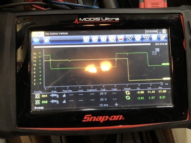
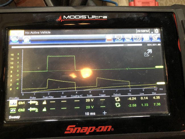
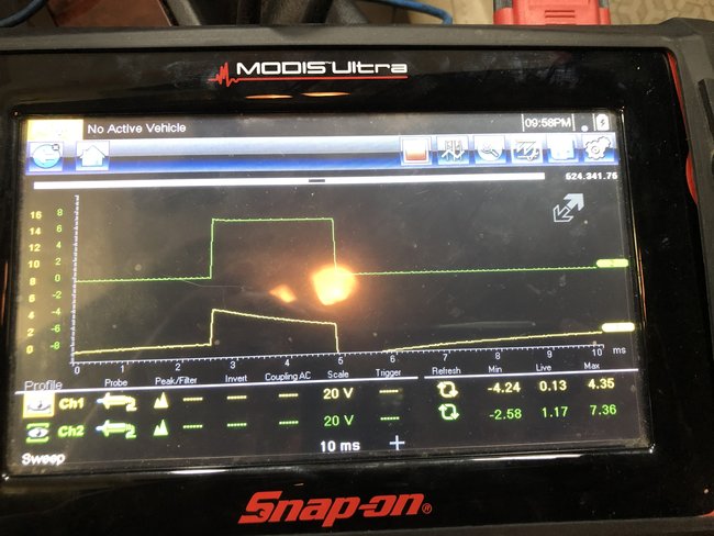
The engine control module (ECM) uses the generator turn ON signal circuit to control the load of the generator on the engine. A high side driver in the ECM applies a voltage to the voltage regulator. This signals the voltage regulator to turn the field circuit ON and OFF. The ECM monitors the state of the generator turn ON signal circuit. The ECM should detect low voltage on generator turn on signal circuit when the ignition is ON and the engine is OFF, or when the charging system malfunctions. With the engine running, the ECM should detect high voltage on the generator turn on signal circuit. The ECM performs key ON and RUN tests to determine the status of the generator turn on signal circuit.

Conditions for Running the DTC

Key ON Test
No generator, crankshaft position (CKP) sensors, or camshaft position (CMP) sensor DTCs are set.
The ignition is in RUN position.
The engine is not running.

RUN Test
No generator, CKP sensors, CMP sensor DTCs are set.
The engine is running.

Conditions for Setting the DTC

During the key ON test, the ECM detects high voltage on the generator turn on signal circuit for 5 seconds.
During the RUN test, the ECM detects low voltage on the generator turn on signal circuit for 15 seconds.

Action Taken When the DTC Sets

The ECM will command the charge indicator and or warning message to be illuminated on the instrument panel cluster (IPC) and the driver information center (DIC), if equipped.
The ECM will not illuminate the malfunction indicator lamp (MIL).
The ECM will store conditions, which were present when the DTC set as Fail Records data only.

Conditions for Clearing the DTC

A current DTC will clear when the conditions for setting the DTC are no longer met.
A history DTC will clear after 40 consecutive warm-up cycles have occurred without a malfunction.

Circuit/System Testing

1. Ignition OFF, disconnect the harness connector at the generator.
2. Ignition ON, test for less than 1 volt between the generator turn on signal and ground.

If greater than the specified range, test the generator turn on signal circuit for a short to voltage. If the circuit tests normal, replace the ECM.

3. Engine running, test for greater than 3.5 volts between the generator turn on signal and ground.

If less than the specified range, test the generator turn on signal circuit for a short to ground, an open or a high resistance. If the circuit tests normal, replace the ECM.

4. If the circuit tests normal during the ignition ON/RUN tests, replace the generator.

Repair Instructions

Perform the Diagnostic Repair Verification after completing the diagnostic procedure. See: A L L Diagnostic Trouble Codes ( DTC ) > Verification Tests


Generator Replacement (LZ4) Generator Replacement (LZ9) Generator Replacement (LY7) Generator Replacement (LE5)
Mar 6, 2020 at 5:12 PM
Avatar
JAYJAY3
  • MEMBER
  • 24 POSTS
The Delco replacement ECM was flashed at the dealer to the latest version software., newer than what is in the original ECM. the car charging system malfunctions the same with both ECM's, although I did not run the lab-scope on the old one.I will get started going through what you sent me now. I will update with answers when I have them.
Mar 6, 2020 at 5:21 PM
Avatar
ASEMASTER6371
  • CERTIFIED EXPERT
  • 52,796 POSTS
Sounds good.

Roy
Mar 6, 2020 at 5:44 PM
Avatar
JAYJAY3
  • MEMBER
  • 24 POSTS
Hi Roy. I solved the p0621. engine running - the t pin i used to check voltage at the ecm on the orange wire must have shorted to a pin next to it. I had B+ on the orange wire KOEO with the alt unplugged - at the alternator. After the t pin was removed I get 4.01volts. I read that as correct for step 3 in circuit testing. Step 2 was 0.01 volts, I also read that as good. What I have left to figure out is low charging. I reran the lab scope test orange wire + yellow pattern, and it looks more like I would expect. I still drive the battery voltage down below 11 volts at Idle. I get to about 12.3Volts if I turn ALL accesories off. loads on I slowly drive the voltage down even at 2000 RPM. I will add the patterns from cell in a minute.

Mar 6, 2020 at 6:23 PM
Avatar
JAYJAY3
  • MEMBER
  • 24 POSTS
Scope pattern engine running, idle, orange = yellow.
Mar 6, 2020 at 6:39 PM
Avatar
ASEMASTER6371
  • CERTIFIED EXPERT
  • 52,796 POSTS
Good find. I am concerned that the short you found may have damaged the alternator.

Roy
Mar 6, 2020 at 7:08 PM
Avatar
JAYJAY3
  • MEMBER
  • 24 POSTS
It is possible, but it seams to me that the alternator charges like 20 amps or something low like that. The scope pattern looks normal to you then? I still can not show charge by turning the l terminal on with the scan tool. I am wondering if the scan tool can actually do it. Would you expect to see B+ on the L terminal of alt when L terminal turned on with scan tool?
Mar 6, 2020 at 7:20 PM
Avatar
JAYJAY3
  • MEMBER
  • 24 POSTS
Okay, I swapped the alternator. No change. I really don’t understand this... I rechecked the voltages and waveform's. I have correct voltages at the orange wire, 4.01 volts. I re ran the voltage drop test on the orange and grey wire. I had 0.40 volts on both wires with 3- 1157 bulbs as a load, both fulminates for each bulb lit. My jumpers are not the greatest so I believe that is okay for what we are doing. Both ECM’s provide the same waveform.
Mar 7, 2020 at 10:34 AM
Avatar
ASEMASTER6371
  • CERTIFIED EXPERT
  • 52,796 POSTS
Okay, .4 is more than it should be. It should be no greater than .2 volts on the load test.

Roy
Mar 7, 2020 at 12:30 PM
Avatar
JAYJAY3
  • MEMBER
  • 24 POSTS
Okay, I agree with you. Does that give me charging at about 10-15 amps though? Or partial charging operation? I will run them pin to pin then and get back to you. What did you think about the wave forms? Are those normal?
Mar 7, 2020 at 3:06 PM
Avatar
ASEMASTER6371
  • CERTIFIED EXPERT
  • 52,796 POSTS
It is hard to tell from here because the pictures are so small.

Are you using a load pro to test the wires?

Roy
Mar 7, 2020 at 3:10 PM
Avatar
JAYJAY3
  • MEMBER
  • 24 POSTS
No, a volt meter and jumper wires.
Mar 7, 2020 at 3:45 PM
Avatar
ASEMASTER6371
  • CERTIFIED EXPERT
  • 52,796 POSTS
That does not load test a circuit.

Load pro is a set of leads for your meter that will load test the circuit. Go to YouTube and type in load pro by Dan Sullivan. I have used it for years.

Roy
Mar 7, 2020 at 3:50 PM
Avatar
JAYJAY3
  • MEMBER
  • 24 POSTS
You can load test a circuit by unplugging both ends, providing 12 volts on one end, a ground on the other end with a load, and checking the voltage drop across your original wire. I use 3 1157 bulbs with both Filaments on to accomplish the load. I had 0.40 volt drop on a loaded circuit. A load pro is nice, I agree, maybe I will look into buying one. I agree that .40 is high, but I have a hard time thinking that it is enough to cause my problem. I can certainly overlay the harness, pin to pin though. Do you think the wave form included looks correct?
Mar 7, 2020 at 5:02 PM
Avatar
JAYJAY3
  • MEMBER
  • 24 POSTS
Yellow trace is orange wire.
Mar 7, 2020 at 5:03 PM
Avatar
ASEMASTER6371
  • CERTIFIED EXPERT
  • 52,796 POSTS
Yes, that is better. Looks good.

You only need a 194 bulb as it is 5 ohms. That is enough to load a circuit.

Roy
Mar 8, 2020 at 1:18 AM
Avatar
JAYJAY3
  • MEMBER
  • 24 POSTS
Do you think the 0.40 voltage drop is my charging problem? Also, I can hear the alternator whine a bit when I function test the L terminal with the scan tool, like it is turned on. Here is a question, could the amp pick up be faulty without setting a code? Also, how does the ECM know when to turn on the alternator, and for what current output?
Mar 8, 2020 at 6:16 AM