Alternator burned now problems ensue?

Tiny
LEPRIKAAN
  • MEMBER
  • 2011 JEEP GRAND CHEROKEE LAREDO
  • 5.7L
  • V8
  • 4WD
  • AUTOMATIC
  • 120,000 MILES
The vehicle listed above is a Cherokee Laredo. I parked the car for about 2 hours and when I came back, I started it and was idling for about 5 minutes while I was preparing to leave. I noticed a whirring noise and some smoke; I popped the hood and saw a red hot ember within the alternator so I got back in and reached for the start/stop button. As soon as I touched the button the battery light came on, I pressed the button and everything went black. I towed the car back home and proceeded to diagnose.
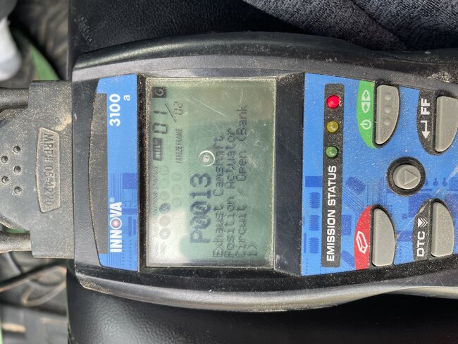
I replaced the alternator with a used one and put in a new AGM battery, started the car and was presented with a CEL. I put my Innova code reader on and got P0013: Exhaust Camshaft Position Actuator Circuit / Open Bank 1. I’ve been racking my brain to figure this out. I’ve pulled the intake manifold off and found bad/bare wires at the VVT solenoid, I repaired/mended the wires where it showed copper and ran continuities on both wires from before and after my mended spots, I then put the manifold back together. Started the car and got the same code. I pulled the manifold back off and pulled the VVT solenoid out. I ran a continuity test on the solenoid about 5 times and it was flat line, so I changed the multimeter to duty cycle and tested the solenoid, it was flat. I tested yet again on continuity, and it registered, every test after has registered with continuity. I put the solenoid to 12v to check for actuation, it actuates but I’m not sure if it’s fully opening. I left the whole thing where it is and ordered a new solenoid and jumper harness. I’m waiting on the new harness to arrive before I do anything further.

My question is how do I identify all the wires coming out of the PCM? It has 4 big plastic connectors coming out and lots of wires in each.
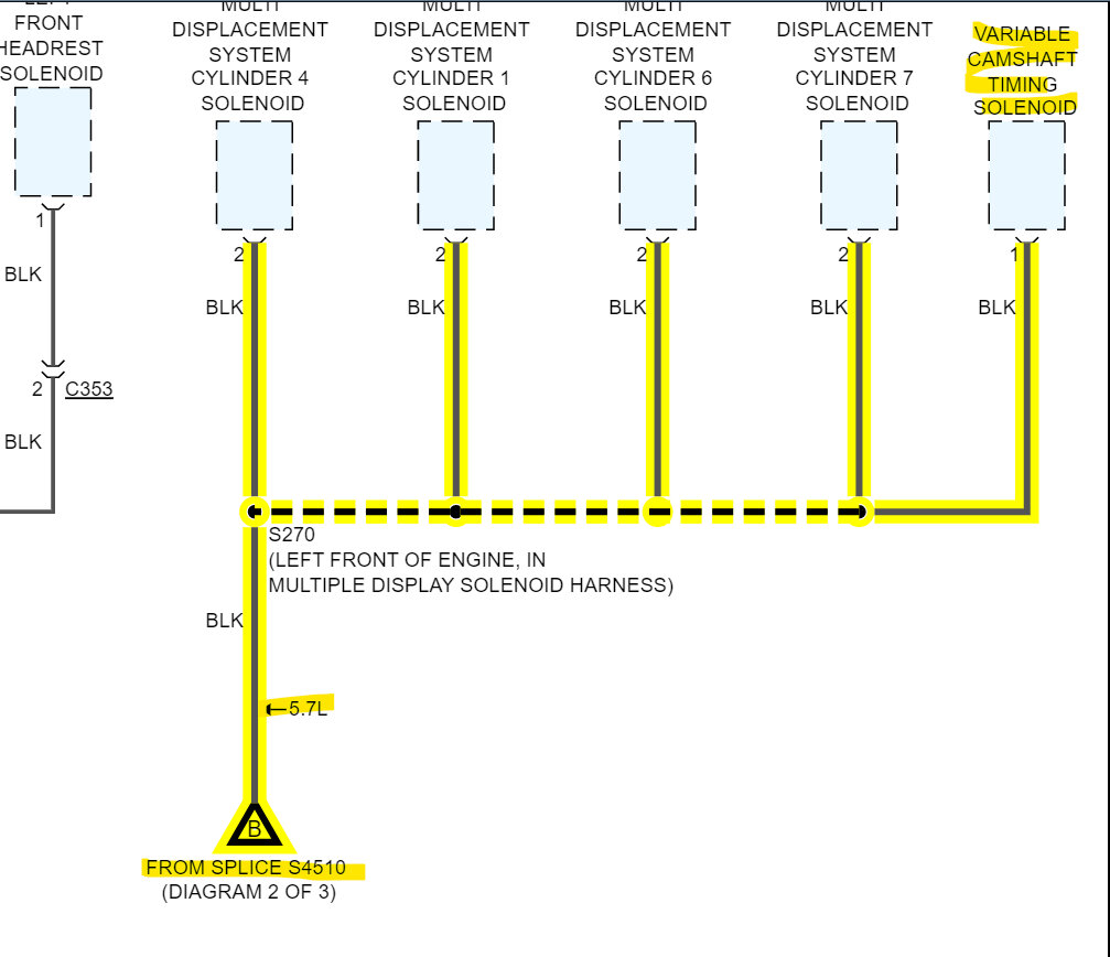
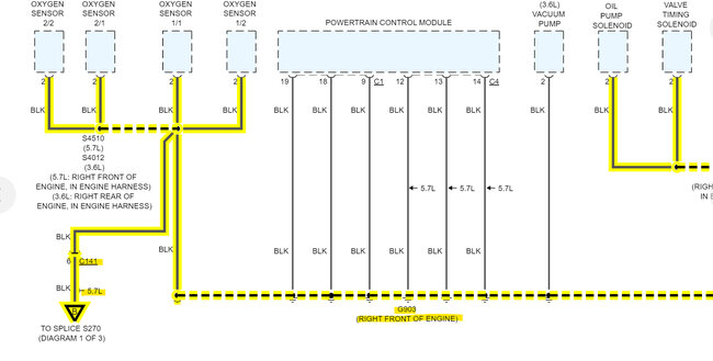
I have sourced a flow chart diagram of the engine electrical, but this doesn’t help me to single out the wires at the PCM side. My worry is that it’s a burn/broken wire further down in the jacket where I can’t see or reach, but if I can pinpoint the wires at the PCM side, I can in theory jump past the bad wire with a fresh wire, therefore saving thousands in repairs and having my vehicle running again.
Saturday, May 27th, 2023 AT 11:23 AM
54 Replies

Tiny
AL514
  • MECHANIC
  • 4,793 POSTS
Hello, yes, we can pull up a wiring diagram for the ECM for you. Just going through the information, you provided. If the alternator was that hot inside, chances are that the diode set may have fried as well, but you won't have any AC voltage ripple now with a new alternator. Also, your assumption of further wire damage is most likely correct. Let me pull up the ECM diagrams for you.
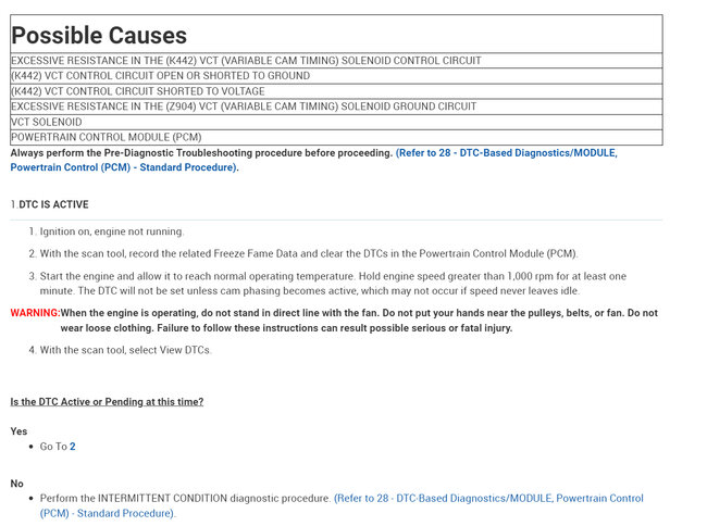
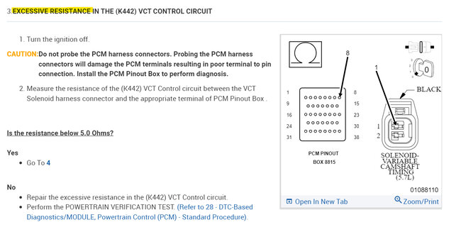
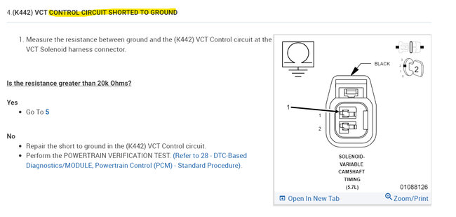
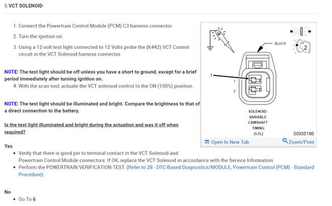
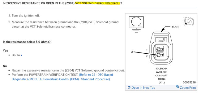
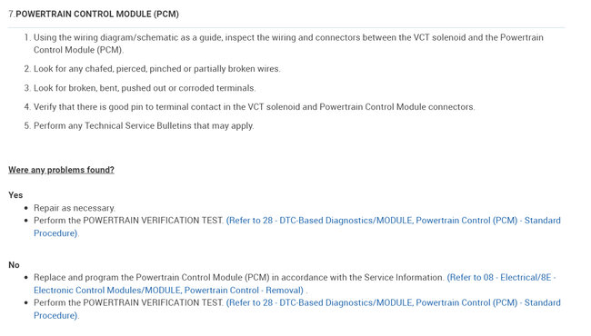
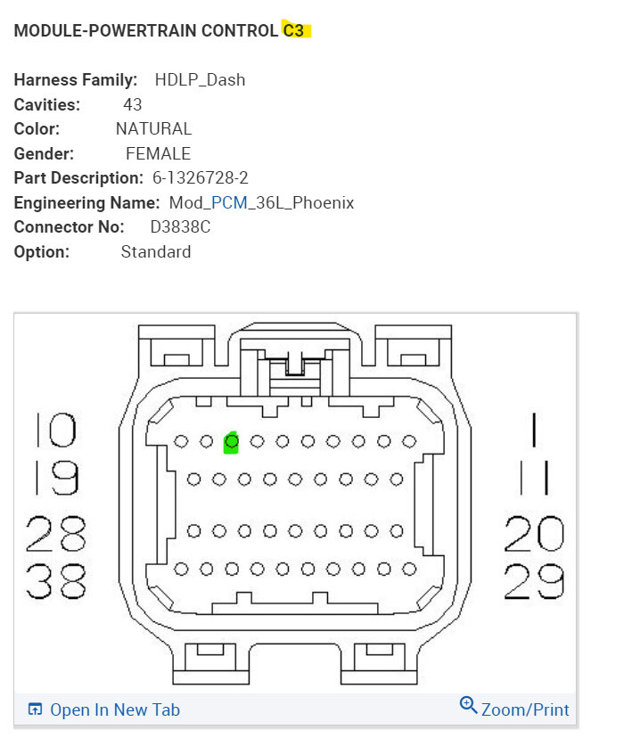
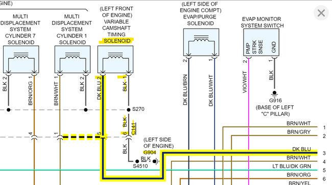
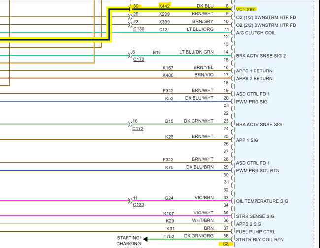
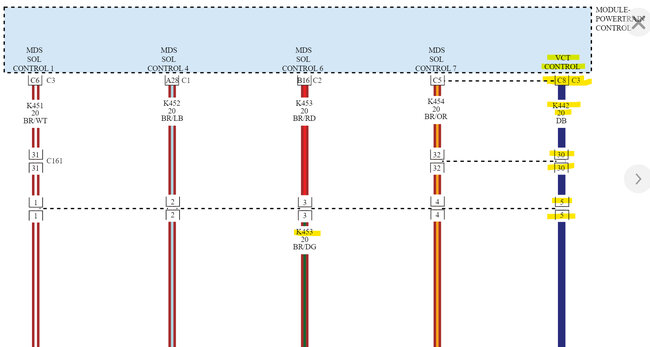
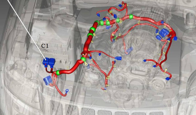
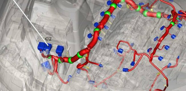
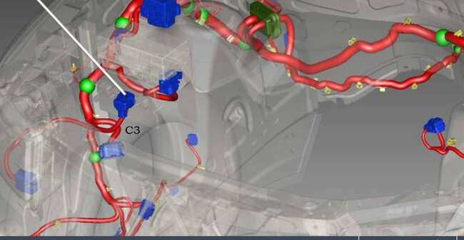
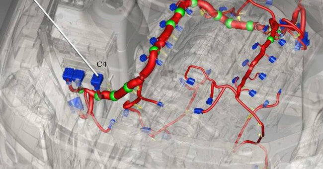
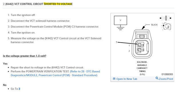
Diagrams 1 to 8 are the flow chart for checking the rest of the circuit for shorts to Ground, shorts to power, and resistance in the circuit to the ECM, which I'm also getting the diagrams for, as well as the ECM connector C3 which is where the control wire for the solenoid runs to. It looks like this is a power side switched circuit, which I'm not sure why they would control it that way, but they did. Some of the flow chart tests you already did. But at least you'll have them, Hopefully the ECM driver for the solenoid didn't burn out.
Was this
answer
helpful?
Yes
No
Sunday, May 28th, 2023 AT 1:12 PM
Tiny
LEPRIKAAN
  • MEMBER
  • 29 POSTS
Awesome, I appreciate all and any help I can get on this. I am basically stranded out in the mountains until I can get this whole thing fixed.
Was this
answer
helpful?
Yes
No
Sunday, May 28th, 2023 AT 1:39 PM
Tiny
AL514
  • MECHANIC
  • 4,793 POSTS
Okay, refresh this page, I added some information in my last post.
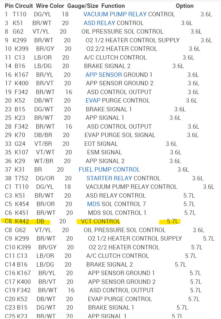
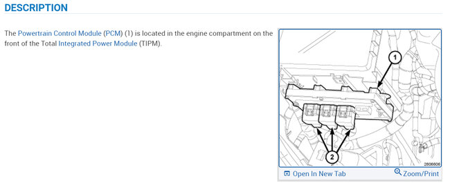
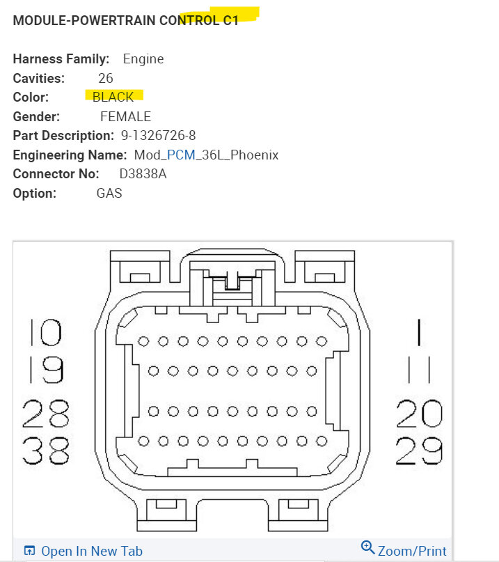
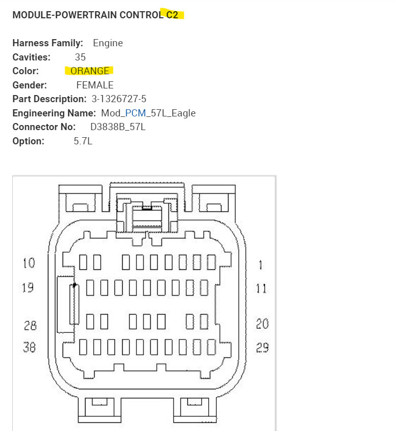
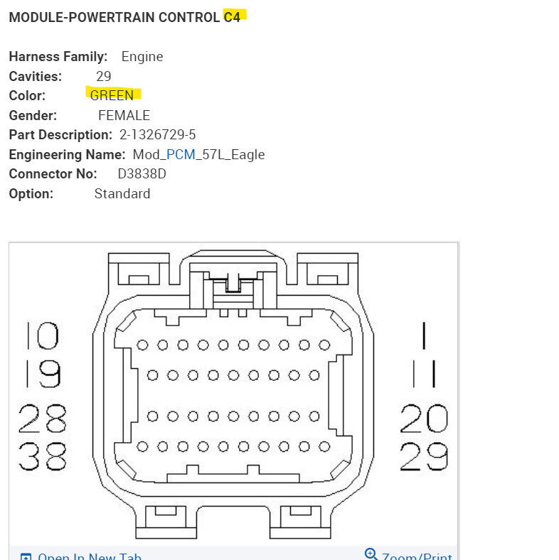
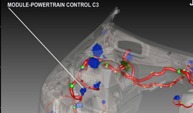
Okay, ECM connector C3 pin 8 (dark blue wire) is the Solenoid control wire. I've added the other ECM connectors so you can find C3 easier, C1 is black, C2 is orange, C3 natural, C4 is green. Hopefully this service info is all correct.
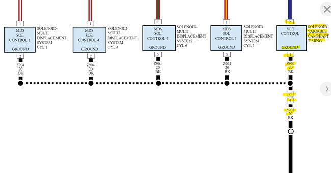
But you can see in diagram 3, the solenoid has a constant Ground and is power side switched by the ECM. Hopefully they put a resistor inside the ECM to protect it from shorts to Ground but knowing Jeep they probably didn't. The 4th diagram shows the C3 connector pin 8 VCT SIG, there is that K442 connector and I also saw a C141 connector on diagram 3. I will see if I can locate that. But as for circuit testing, with the key Off, you can follow the flow chart and unplug C3 and check with your meter on Ohms setting for any continuity to Ground with the Solenoid unplugged. That will eliminate the ECM and solenoid for now and concentrate on the wiring alone to begin with. There is a key on test on Flow chart number 2. With this being a 2-wire circuit, it shouldn't be too difficult to trace down any other problem areas, I will post that C141 if its listed in service info for you.
I've added OEM diagrams 10 and 11 for you because I don't see a C141 connector listed.

Okay, they don't have this connector listed by C141, I know this is confusing, but they have it listed by circuit number,
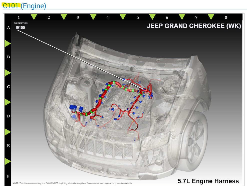
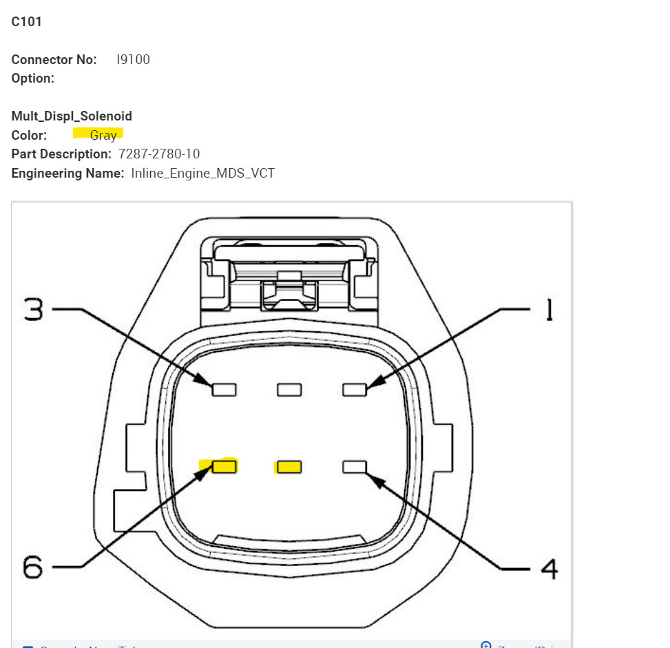
Diagram 12 shows its location (C101) and diagrams 13, 14 are one half of the connector,
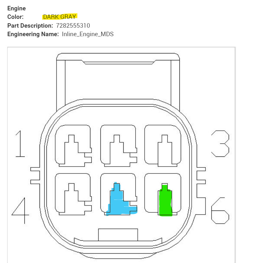
and 15, 16 are the other half of the connector.

They should be grey and dark grey in color, 6 pins, it's an inline connector that both the wires for the Solenoid run through. Still a dark blue wire (pin 5), and the Ground is black (pin 6).
Was this
answer
helpful?
Yes
No
Sunday, May 28th, 2023 AT 1:44 PM
Tiny
LEPRIKAAN
  • MEMBER
  • 29 POSTS
Awesome information. I appreciate it more than you know!

I'm still unsure how to identify the PCM connectors. So, if I unplug them and look on the inside, they'll have color's or?
The outside of the housing is all black on all four. If the above is correct, when unplugged, the inside of C1 will have a black gromet and C2 will have an orange gromet etc?
Was this
answer
helpful?
Yes
No
Sunday, May 28th, 2023 AT 9:06 PM
Tiny
LEPRIKAAN
  • MEMBER
  • 29 POSTS
Also, is it safe to unplug the PCM connectors while the battery is disconnected? Will I need to resync anything for any reason, eg. I read that if I unplug the CMP sensor that it will have to be resync'd to the ECM or something to that end. I'm taking a guess and thinking the ECM is the same as the PCM. Again, I just can't be sure.

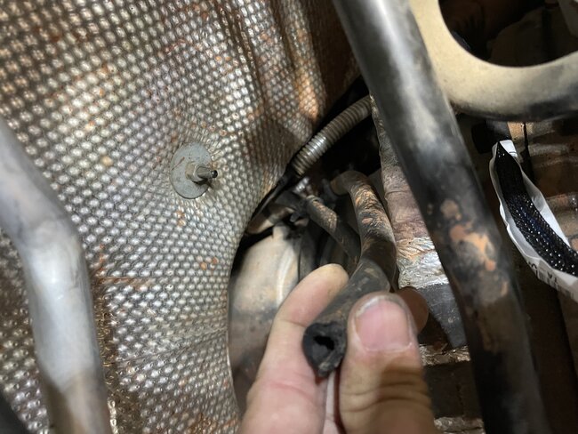
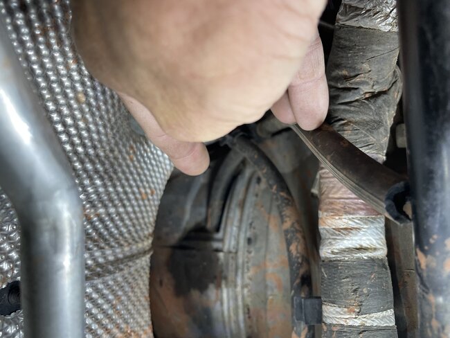
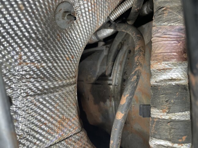
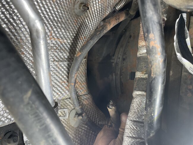
On a side note for later, while I have the manifold removed but resting in place, I was looking at the back side of the engine by the firewall for the ground, and found 2 black rubber hoses coming from the transmission that aren't connected to anything, they're just roaming around the engine bay loose like wild children. Can't for the life of me find a rhyme or reason to them but they're definitely attached to the trans, I can see one connection from the engine bay. The loose ends are rubbish, one has a hard plastic connector smelded into the tip, the other hose end looks like it's spent a life sentence in rubbing alcohol and is deteriorated/dry rotten. I can post photos if needed for any of the above.
Was this
answer
helpful?
Yes
No
Sunday, May 28th, 2023 AT 9:21 PM
Tiny
AL514
  • MECHANIC
  • 4,793 POSTS
Each PCM connector itself should be a different color, but it might be referring to an inside grommet. I'm just going by the service information I have available. C3 should be the 3rd from the left I believe anyway, but you can verify C3 by checking some of the wiring colors if you're unsure. For example, pin C1 is a dark green wire with a yellow stripe.

The cam sensor issue you're thinking of is a cam/crank variation relearn procedure. That would need to be done if you replaced components, and the ECM needed to relearn the new positions of camshafts, crankshaft sensors, valve train parts, for example.

You're just going to be unplugging the one connector to verify there are no shorts to Ground or power that you can't see, instead of pulling the entire harness apart, you can do end to end testing and save a ton of time and headache. Since its really only going to be that one wire that controls the solenoid, you'll just be testing from the solenoid plug to the ECM plug. The Flow Chart should be very accurate. Sometimes they tend to have you doing tests that you may have covered already, because the flow charts are designed by engineers, not technicians. Some techs will do loaded voltage drop testing, but since you've already found some wire missing insulation, you know it's a possibility at this point for there to be more of that. You can see from the picture of C101, just about where the entire harness area you'll be needing to check is. From the back of the engine on the driver side to the ECM, I will also see if I can find this Ground location G904 if you have not already found it.

And that color for C3 being "natural", I'm sure is some tan type of color. And on the pinout sheet for C3 take note of where it says 5.7 Liter vs 3.6 Liter on the right side. If you want to post pictures of the rubber hoses you're referring to, that's fine.
Was this
answer
helpful?
Yes
No
Monday, May 29th, 2023 AT 10:35 AM
Tiny
AL514
  • MECHANIC
  • 4,793 POSTS
I want to make sure you these correct, do you have 4 ECM connectors or just 3? Some diagrams and pictures are showing the 5.7liter missing what looks like the 3rd connector over, but that might just be the service info.
This is what I'm seeing. Hopefully they're the same for you.
Was this
answer
helpful?
Yes
No
Monday, May 29th, 2023 AT 11:44 AM
Tiny
LEPRIKAAN
  • MEMBER
  • 29 POSTS
Yes, my PCM definitely has 4 plugins they appear to be symmetrical to each other and the body/housing is all black on all 4. I will unplug one to check for color and compare. Then I’ll check for continuity up to the plug after verifying colors/pins.
Was this
answer
helpful?
Yes
No
Monday, May 29th, 2023 AT 12:02 PM
Tiny
AL514
  • MECHANIC
  • 4,793 POSTS
Okay, the 3rd over should be the one you want. And not sure if I asked, but what scan tool do you have access to? Just wondering if you can pull up live engine data PIDs
Here is the Ground location for the timing solenoid.
Was this
answer
helpful?
Yes
No
Monday, May 29th, 2023 AT 12:14 PM
Tiny
LEPRIKAAN
  • MEMBER
  • 29 POSTS
This is the reader and the code. The Jeep itself has a reader built into the stereo but cannot access it while it’s all powered down.
Was this
answer
helpful?
Yes
No
Monday, May 29th, 2023 AT 1:40 PM
Tiny
AL514
  • MECHANIC
  • 4,793 POSTS
I don't see live data on that scanner. Let's see what you come up with during the harness testing.
Was this
answer
helpful?
Yes
No
Monday, May 29th, 2023 AT 2:54 PM
Tiny
LEPRIKAAN
  • MEMBER
  • 29 POSTS
I’m going to begin testing this morning. I am expecting the new jumper harness today, so I’ll disconnect the - and + battery cables, put the new jumper harness in and confirm C3 plug-in by checking color of grommet or by wire color verification. Then I’ll do a continuity test from the C3 pin 8 dark blue as well as the ground black. Does this sound correct?
Was this
answer
helpful?
Yes
No
Tuesday, May 30th, 2023 AT 8:17 AM
Tiny
LEPRIKAAN
  • MEMBER
  • 29 POSTS
Update: I ran the continuity test on both the blue and black from the solenoid end to the PCM plugin and to the shock bolt/ground as well as between the two at each end. Both wires have continuity but not between each other, although on the PCM plugin I couldn’t get continuity, I don’t know if my needle is long enough to make contact or if that pin is borked, so I needle probed the dark blue wire just below the plugin and got continuity. The new jumper harness will be delivered within the next hour. I will then replace the jumper and the solenoid, buckle the intake manifold back down, plug everything back in, connect the positive then the negative on the battery, check oil level and add if needed, then push the button to run mode and clear the code, then push the button to off and start the car, hold rpm above 1k for 1 minute and pray it doesn’t come back.
Was this
answer
helpful?
Yes
No
Tuesday, May 30th, 2023 AT 10:21 AM
Tiny
AL514
  • MECHANIC
  • 4,793 POSTS
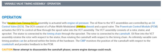
You couldn't get a reading from the pin side of the PCM connector? Can you see the pin inside the connector? I would be concerned that the C3 connector pin did back itself out somewhat, that could happen if that wire got hot. Possibly from those wires shorting out. So, if you can, verify that front pin, pin fitment issues can cause you to chase issues for a long time. With those connectors being hooked up for so many years of usage. And they get hot and cool down and that's how pins don't make contact anymore. And really you have no way to monitor the ECM data to see if the cam timing is changing. What you could do is to monitor that wire with your multimeter after you get everything back together. It's most likely going to be a pulse width modulated circuit, so you will see an average voltage with the multimeter and not a full 12volts all the time. If it's 50% duty cycle, 50 on 50 off, you would average 6ish volts because a meter can only average that voltage. If you were to scope that wire, you would see a 0v to 12volt square wave signal. That would vary depending on how much the ECM is changing the cam timing. But I would really check that ECM connector. With the testing you did on the solenoid, it sounds like it over heated and that's why you got those odd readings.
Solenoids are controlled by PWM to prevent them from overheating. I'd feel bad if that code came back after all the work you have done already. It's really great. Those ECM connectors do come apart if that pin has backed out. They take some time, and you have to be careful with them. Or you could try the pierce again on the dark blue wire and then right to the ECM pin to check continuity. That way at least you'll know that connector has a pin fitment issue.
Was this
answer
helpful?
Yes
No
Tuesday, May 30th, 2023 AT 12:14 PM
Tiny
LEPRIKAAN
  • MEMBER
  • 29 POSTS
Okay, I have everything back together minus the battery cables. I took another look at the PCM plugin side and realized I should’ve been trying the 3rd from the left not the right. It’s a little bit late now but I installed the new solenoid and jumper harness. I plugged everything back in as far as I can tell, doing a double check as I type now.

Before I go any further, I’m wondering what you think my next steps should be.

Also, here are the pictures of the rubber lines coming from the transmission that are messed up.
Was this
answer
helpful?
Yes
No
Tuesday, May 30th, 2023 AT 12:48 PM
Tiny
AL514
  • MECHANIC
  • 4,793 POSTS
I'm not sure what those lines are. I thought maybe at first it was some overflow type line, but it does look like there is a plug in that one end. I'll take a look on all data for any transmission diagrams. I'd say you can start it, let it get up to operating temperature and see if you notice anything abnormal happening. Ill post what I find on the transmission.
Also on your wire checking, there was the black wire grounded for the Solenoid.
I don't see those being any kind of transmission cooling lines, being rubber like that.
Was this
answer
helpful?
Yes
No
Tuesday, May 30th, 2023 AT 1:49 PM
Tiny
LEPRIKAAN
  • MEMBER
  • 29 POSTS
Yes, I checked the ground wire for continuity by probing the wire at the solenoid end and touching the strut/shock mount bolt. I will clear the code and start it now.
Was this
answer
helpful?
Yes
No
Tuesday, May 30th, 2023 AT 1:51 PM
Tiny
AL514
  • MECHANIC
  • 4,793 POSTS
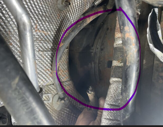
Is this the transmission bell housing?
Was this
answer
helpful?
Yes
No
Tuesday, May 30th, 2023 AT 1:58 PM
Tiny
LEPRIKAAN
  • MEMBER
  • 29 POSTS
Yes, it is.
I cleared the code, and the light comes back with the same code. I’m going to let it get warmed up to operating temperature which I would assume is about 200, 210, and see what happens. I’ll post back ASAP.
Was this
answer
helpful?
Yes
No
Tuesday, May 30th, 2023 AT 2:05 PM
Tiny
AL514
  • MECHANIC
  • 4,793 POSTS
Still P0013? This isn't a Natural Gas vehicle, is it? You can try your pierce tool and clear the code, have a test light or multimeter hooked up to the dark blue wire right at the PCM and start the vehicle, see if you're getting any voltage out of that wire. But you will have to do this quickly, once the code is set it will probably disable that circuit. Being that it is a circuit code, there is a voltage issue somewhere. We need to know if there's any voltage coming out of the ECM to command that solenoid.
I'm also wondering about a cam/crank relearn procedure needing to be done.
Was this
answer
helpful?
Yes
No
Tuesday, May 30th, 2023 AT 2:30 PM

Please login or register to post a reply.

Sponsored links