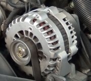
Alternator quit charging

Tiny
LANNY536192
  • MEMBER
  • 1992 DODGE DAKOTA
  • 3.9L
  • 6 CYL
  • 4WD
  • AUTOMATIC
  • 150,000 MILES
In January of this year I replaced the ECM with a rebuilt because the alternator quit charging and I had it tested and it tested good at the time. Pickup ran and worked fine since that time but quit charging again recently. Checked alt. Again and it puts out fifteen plus volts so ordered a replacement ECM that was under warranty. Installed ECM. Charges part of the time and quits after a few miles on our country roads. I have followed your threads on testing at the computer at pin 60 etc. Yesterday I added a jumper wire from the 60 pin position back to the green wire on the alternator when it would not kick in and it immediately started charging 14.8 volts. I thought this indicated a bad wire was causing the problem. I installed the jumper wire. It charged fine for a few minutes and quit again. This morning I removed the jumper wire and stared pickup. It charged for a few seconds and quit again. At this time I tried to jump it again from pin 60 back to the alt. Again and it would pickup.
I am trying to keep from installing older style regulator because of the check engine light issue.
I just cannot make sense of the intermittent coming and going of the charge. It would seem to me that the regulator in the computer would either work or not at all.
Any suggestions would be greatly appreciated.
Lanny
Tuesday, June 13th, 2017 AT 6:11 AM

13 Replies

Tiny
LANNY536192
  • MEMBER
  • 9 POSTS
I miss stated the pin number on the computer I referred to it should have pin 20 on a 60 pin plug block for the computer.
Was this
answer
helpful?
Yes
No
+1
Tuesday, June 13th, 2017 AT 7:21 AM
Tiny
CARADIODOC
  • MECHANIC
  • 33,873 POSTS
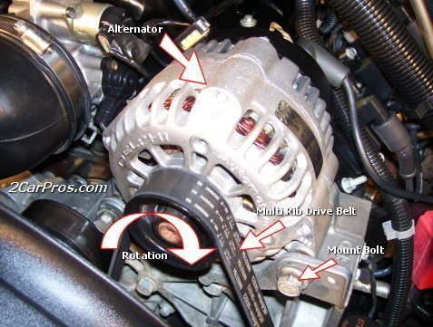
The next time you can catch it not charging, go to the two smaller terminals on the back of the alternator and measure those two voltages. That has to be done with the engine running. One of them should have full battery voltage. The other one is the one that goes to terminal 20 of the engine computer. That one should have less than battery voltage, but not 0 volts. Typically you will find between 4 and 11 volts.

If those two voltages are okay, measure the voltage on the larger output terminal and compare that to the battery's voltage. Tell me what you find for those voltages.

You are right about the check engine light issue. Chrysler was the first manufacturer to use an electronic voltage regulator. It will run the newer alternators just fine, but the computer will detect the open circuit from the alternator, and will turn on the check engine light. With that light always on, you will never know if another problem is detected.
Was this
answer
helpful?
Yes
No
+1
Tuesday, June 13th, 2017 AT 7:02 PM
Tiny
LANNY536192
  • MEMBER
  • 9 POSTS
I have checked the voltage on the two small terminals several times through out this problem. The first one like you say will typically have 13.8 to 14 volts the same as the battery voltage. The second one varies from 7.8 to 9.0 usually. The big wire will have 13.7 plus usually. Today I thought I had found the problem with the connection of the green wire in the 20 pin position. I could unplug the harness at the computer and wiggle it around and it would start and charge fine only to quit again thirty minutes later etc. I tried to clean the crimp sleeve for pin 20 on the green wire and that seemed to work for a while but eventually quit again. So I unplugged the harness again and sprayed WD 40 on it and plugged it back in and wiggled it around trying to make good connections on all. At this point it would not even fire when I tried to start it. So I unplugged the harness again and sprayed it with contact cleaner and blew it out with air pressure. Put it back together and it fired right up and I drove it ten miles home with it charging all the way only to quit when I pulled into driveway. I still think it is all related to the problem with the green wire on pin 20 right at the computer but I am stuck about what else to do to it. The green wire seems to be good, no breaks and the pin that is attached to it looks fine but I must be missing something.
Was this
answer
helpful?
Yes
No
Tuesday, June 13th, 2017 AT 7:35 PM
Tiny
CARADIODOC
  • MECHANIC
  • 33,873 POSTS
If you found 13.8 to 14 volts on the first terminal, the system was charging, so there was no defect at that time. You have to catch it while the system is not working. The one thing you cannot get into to measure is the terminal at the computer. Those rarely cause a problem unless someone poked a test probe it too far and spread it, but this is where the two voltage readings will tell the story. If there is a break anywhere in that wire going to the voltage regulator, (terminal 20), you will find exactly the same voltage on both smaller terminals on the alternator. That break can be in the wire, the voltage regulator itself, the terminal at the computer, or most commonly, a corroded pair of terminals in the connector between the engine and the body.

Those three voltage readings will tell us which circuit has the problem. Be aware the lower the voltage on the control wire, (terminal 20), the larger electromagnet is being made inside the alternator, and that is when the most field current is flowing through those smaller wires. A bad voltage regulator inside a Chrysler engine computer is very uncommon, and to have two of them is really rare. Even more rare is for one to be intermittent. Given the history of charging okay for a short period of time, then going to failure mode, a real good suspect is one of the smaller wires to the alternator got pierced some time ago, and now the copper has corroded away, but not quite to the point of a total failure, yet. When asked to generate its maximum output current, field current through those two smaller wires will be close to three amps. That is not much, but if connector terminals are corroded, or if one last strand of wire is just barely intact yet by a corroded spot, that couple of amps can be enough to heat up a bad connection and make it fail.
Was this
answer
helpful?
Yes
No
+1
Tuesday, June 13th, 2017 AT 8:16 PM
Tiny
LANNY536192
  • MEMBER
  • 9 POSTS
Thank you for the information. Will try to get more current information today and be more specific. Also, I am sorry for the long delay in this response, I am located in the central time zone and had to call it a day yesterday.
I agree with you about the rarity or likelihood of two bad ECM's in a row.
Was this
answer
helpful?
Yes
No
Wednesday, June 14th, 2017 AT 3:51 AM
Tiny
LANNY536192
  • MEMBER
  • 9 POSTS
I checked this morning and viewed the following voltages. Switch off at battery 12.8 v.
Switch on @ battery 12.78 not running
@ alt. Large wire 12.7 v.
Small wires both showed 0 v.
Switch on engine running. @ Alt. Large wire 12.7 v.
Small wires blue wire 12.5 v.
Small wire green 12.4 v.
Not charging.
I never tried unplugging the harness wire and reattaching to see if it would pickup and charge as I wanted to tell you the voltages when not charging.
Was this
answer
helpful?
Yes
No
Wednesday, June 14th, 2017 AT 5:51 AM
Tiny
LANNY536192
  • MEMBER
  • 9 POSTS
Today I decided to start the pickup again and check for charging. It wasn't charging when the voltages were as stated above. With it running I then tried to check for broken or loss wires at the computer. When I wiggled the plug of the harness around gently to check it the engine backfired and died. So I disconnected it again and looked carefully at the computer pins and the clamp sleeves in the harness but really didn't see any obvious problem. When I plugged it back in I tried to make sure everything went together as best as I can because you really can't see in it. I snugged it down tight and started it and it immediately started charging 13.8 to 14 volts. I drove it to the farm and back and it seemed to work well. My question is would the green wire at pin 20 which I assume is a ground wire that messes up part of the time for the charge circuit also be what grounds the computer for its engine functions as well? When it caused the backfire and stall. Does this ground the computer as well as the alternator?
Thank you for what ever advice you can give.
Was this
answer
helpful?
Yes
No
Wednesday, June 14th, 2017 AT 4:30 PM
Tiny
LANNY536192
  • MEMBER
  • 9 POSTS
Hope you can respond to my last question concerning the green wire. If it continues to come and go as it has what would be your recommendation be to fix the problem? I would rather not put the old style regulator on if I can avoid it.
Thanks for any help.
I apologize for not being to keep this conversation more current but we are evidently in two very different time zones. My days start at 4am central time and by 10pm my time I'm done in.
Was this
answer
helpful?
Yes
No
Thursday, June 15th, 2017 AT 4:28 PM
Tiny
CARADIODOC
  • MECHANIC
  • 33,873 POSTS
I'm in the middle of Wisconsin, so I'm in the central time zone too. My problem is I had a major house fire three years ago, so I don't have internet at home. I have to drive 21 miles to town to sit in my library's parking lot and use their wireless internet. Sometimes I skip a day to save a few bucks on gas.

Don't worry about voltage readings when the engine is not running. The alternator's field circuit gets its 12 volts from the automatic shutdown, (ASD), relay, and the computer turns that on when the engine is rotating, (cranking or running). That relay also sends current to the injectors, ignition coil, and fuel pump or pump relay.

That green wire has nothing to do with running the Engine Computer. It is strictly the control wire for the alternator. If you are familiar with the older system with that electronic voltage regulator, every wire under the hood of those early '70s cars that was dark blue got 12 volts on it when the ignition switch was on. That included a blue 12 volt feed to one brush on the alternator, and a blue 12 volt wire to the regulator. That wire at the regulator was to power the internal circuitry, and that was where the regulator monitored system voltage.

For current to flow through any circuit, it has to have a complete path from and back to the battery. We have the 12 volts up to the first brush on the alternator, then for the rest of the circuit, current flows through the second brush, through the green wire, through the regulator, then to ground and back to the battery.

Chrysler kept the green wire on the newer vehicles for the control wire. Your switching is done by that ASD relay instead of the ignition switch. The rest of the system is the same except the voltage regulator is built into the Engine Computer. That was done so the regulator could modify target charging voltage for a variety of conditions. The old electronic units had temperature compensation built in. With the regulator in the computer, it can adjust charging voltage in anticipation of the AC compressor turning on, changes in battery temperature, and it can stop the alternator from working momentarily when it needs that five horse power, like during wide-open-throttle.

Once the current flows through the regulator, it goes to ground through the pair of "power" ground wires. "Power" grounds just means they are for the high-current circuits including injectors, relays and solenoids, and anything else that will be pulsing or varying. There's two other "signal" ground wires for sensor circuits. Each ground wire has a duplicate in case one has a less-than-perfect connection.

The regulator monitors system voltage on one of the multiple 12 volt feed wires to the computer. That circuit doesn't cause charging problems because it is also used for other functions. Typically the engine won't even run when any of those 12 volt feeds is missing, so you'd be diagnosing a no-start condition, not a charging problem.

Getting back to your truck, the secret is there is almost the same voltage on the two field terminals. No voltage is being dropped across the field winding. That means no current is flowing through it. No current means no magnetic field is being built up in that field winding, so no output current will be generated.

There's two ways to find the cause of the no-charge. One is to measure the voltage on that green wire in various places. There's a connector in the harness between the engine and the body, and there's the terminal at pin 20 at the computer. You will find the same 12.4 volts all the way along that wire up to the break, then it will be 0 volts after that break. The cover can be popped off the computer connector, then you can back-probe the green wire there. If you find 12.4 volts right up to the computer, either that terminal is spread and not making good contact, or the regulator circuit is indeed open again. If the terminal is spread, pushing and twisting on the wire will usually get it to make intermittent contact long enough for you to verify it is having some effect. You might also suspect that wire is burned off the terminal.

The second way to find the break is to ground the green wire in various places. That will "full-field" the charging system and make it run wide open by bypassing the regulator, just like we did on the '70s systems. Turn on the head lights or connect the voltmeter to the battery so you have something to observe to show the charging system is working. You can also listen to the engine being loaded down and the increased whine of the alternator. System voltage will go too high when you do this, so do it just long enough to determine the result. Full-fielding is done as part of a charging system test to determine if the alternator is capable of developing its rated output current. If you back-probe the wire right at the computer, then ground that wire, and system voltage rises a lot, that tells you the green wire is good up to that point.
Was this
answer
helpful?
Yes
No
+1
Thursday, June 15th, 2017 AT 10:19 PM
Tiny
LANNY536192
  • MEMBER
  • 9 POSTS
Thank you much for all the info, I'll check some of this out more closely today. Also I really appreciate your diligence and patience with me. Hope all is well in Wisconsin. I'm in Nebraska. At least we're blessed with two great football programs. Thanks
Was this
answer
helpful?
Yes
No
Friday, June 16th, 2017 AT 4:36 AM
Tiny
KEN L
  • MASTER CERTIFIED MECHANIC
  • 47,643 POSTS
Please let us know what happens, we are interested to see what it is.

Cheers, Ken
Was this
answer
helpful?
Yes
No
Monday, June 19th, 2017 AT 10:07 AM
Tiny
LANNY536192
  • MEMBER
  • 9 POSTS
Ken, I was able to find that the green wire had a bad connection in one of the junction plugs between the alt. And the computer that I wasn't seeing before. Rather than tear the whole plug apart I just rewired the green wire around it. The alternator works fine now and usually stays around 13.5 or above while I am in route to the farm and back. Must be by aging vision that messed me up for a time. Because it was obvious with more light on it.
Thanks for your patience with me and all your help and info.
God Bless and happy trails,
Lanny
Was this
answer
helpful?
Yes
No
Monday, June 19th, 2017 AT 6:34 PM
Tiny
KEN L
  • MASTER CERTIFIED MECHANIC
  • 47,643 POSTS
Good to hear, please use 2CarPros anytime we are here to help.

Cheers, Ken
Was this
answer
helpful?
Yes
No
Monday, June 19th, 2017 AT 9:08 PM

Please login or register to post a reply.

Sponsored links