ABS function on scanner not working?

Tiny
ALAN POSEY
  • MEMBER
  • 2004 PONTIAC GRAND PRIX
  • 3.8L
  • V6
  • TURBO
  • 2WD
  • AUTOMATIC
  • 105,000 MILES
Car listed above is a GTP model. I recently ordered an ANCEL FX6000
Scanner and the company verified that it would provide the ABS auto bleed function for my car. It arrived in the mail today and I tried performing the ABS auto bleed function but when I press OK to start bleed function it says it cant perform the task due to DTC (diagnostic trouble codes). Well on the same scanner I backed up a few steps and clicked on read DTC codes and it says there are no pending DTC codes so then I cleared everything, and reset everything, then unhooked the battery for 30 minutes and tried it again and it said the same thing. I even tried 2 other scanners and they are all saying 0 codes even after multiple drive cycles. Do I have to update software to perform this function, or is it a lost cause, because I have to register the scanner on the company's website in order to update it, and I can't return it after updating it. I hate to waste over $300.00 for something I cant use.. Any ideas?
Wednesday, March 24th, 2021 AT 9:37 PM

3 Replies

Tiny
ASEMASTER6371
  • MECHANIC
  • 52,797 POSTS
Good morning,

Is the ABS light on?

The only thing I can think of is that there is an electrical issue. That is when you cannot clear any codes. With an electrical fault. Codes cannot be cleared. They will remain until they are repaired.

Can you read live data with your scan tool like wheel speed sensors?

I attached the procedure below. Did you follow this procedure?

Roy

ABS Automated Bleed Procedure

Bleeding the ABS System

Caution: Refer to Brake Fluid Irritant in Service Precautions.
See: Brakes and Traction Control > Technician Safety Information > Brake Fluid Irritant Caution

Notice: Refer to Brake Fluid Effects on Paint and Electrical Components in Service Precautions.
See: Brakes and Traction Control > Vehicle Damage Warnings > Brake Fluid Effects on Paint and Electrical Components Notice

Perform a manual or pressure bleeding procedure. Refer to Hydraulic Brake System Bleeding (Manual) or Hydraulic Brake System Bleeding (Pressure) in Hydraulic Brakes. If the desired brake pedal height results are not achieved, perform the automated bleed procedure.

The procedure cycles the system valves and runs the pump in order to purge the air from the secondary circuits normally closed off during normal base brake operation and bleeding. The automated bleed procedure is recommended when air ingestion is suspected in the secondary circuits, or when the BPMV has been replaced.

Automated Bleed Procedure

Notice: The Auto Bleed Procedure may be terminated at any time during the process by pressing the EXIT button. No further Scan Tool prompts pertaining to the Auto Bleed procedure will be given. After exiting the bleed procedure, relieve bleed pressure and disconnect bleed equipment per manufacturers instructions. Failure to properly relieve pressure may result in spilled brake fluid causing damage to components and painted surfaces.

1. Raise the vehicle on a suitable support. Refer to Vehicle Lifting.
2. Remove all four tire and wheel assemblies. Refer to Tire and Wheel Removal and Installation.
3. Inspect the brake system for leaks and visual damage. Refer to Brake Fluid Loss or Symptoms - Hydraulic Brakes. Repair or replace as needed.
4. Inspect the battery state of charge. Refer to Battery Inspection/Test.
5. Install a scan tool.
6. Turn ON the ignition, with the engine OFF.
7. With the scan tool, establish communications with the EBCM. Select Special Functions. Select Automated Bleed from the Special Functions menu.
8. Bleed the base brake system. Refer to Hydraulic Brake System Bleeding (Manual) or Hydraulic Brake System Bleeding (Pressure) in Hydraulic Brakes.
9. Follow the scan tool directions until the desired brake pedal height is achieved.
10. If the bleed procedure is aborted, a malfunction exists. Perform the following steps before resuming the bleed procedure:
- If a DTC is detected, refer to Diagnostic Trouble Code (DTC) List and diagnose the appropriate DTC.
- If the brake pedal feels spongy, perform the conventional brake bleed procedure again. Refer to Hydraulic Brake System Bleeding (Manual) or Hydraulic Brake System Bleeding (Pressure) in Hydraulic Brakes.

11. When the desired pedal height is achieved, press the brake pedal in order to inspect for firmness.
12. Remove the scan tool.
13. Install the tire and wheel assemblies. Refer to Tire and Wheel Removal and Installation.
14. Inspect the brake fluid level. Refer to Master Cylinder Reservoir Filling in Hydraulic Brakes.
15. Road test the vehicle while inspecting that the pedal remains high and firm.
Was this
answer
helpful?
Yes
No
Thursday, March 25th, 2021 AT 4:50 AM
Tiny
ALAN POSEY
  • MEMBER
  • 15 POSTS
Yes sir, I followed that procedure exactly. There are no broken wires or bad plugs or bad visible connections that I can find. My (guess) is that the problem lies within the EBCM or the Body Control Module. What do you think?
Was this
answer
helpful?
Yes
No
Thursday, March 25th, 2021 AT 6:49 AM
Tiny
ASEMASTER6371
  • MECHANIC
  • 52,797 POSTS
The ABS module, yes but not the BCM.

https://www.2carpros.com/articles/how-to-replace-a-abs-controller

I attached the procedure below for you.

Roy

Electronic Brake Control Module (EBCM) Replacement

Removal Procedure

Caution: Refer to Brake Fluid Irritant in Service Precautions.
See: Brakes and Traction Control > Technician Safety Information > Brake Fluid Irritant Caution

Notice: Refer to Brake Fluid Effects on Paint and Electrical Components in Service Precautions.
See: Brakes and Traction Control > Vehicle Damage Warnings > Brake Fluid Effects on Paint and Electrical Components Notice

Notice: To prevent equipment damage, never connect or disconnect the wiring harness connection from the EBCM with the ignition switch in the ON position.

imageOpen In New TabZoom/Print

1. Turn the ignition switch to the OFF position.
2. Remove the fuel injector sight shield, 3.8L engine only. Refer to Fuel Injector Sight Shield Replacement (L26) or Fuel Injector Sight Shield Replacement (L32) in Engine Mechanical - 3.8L.
3. Remove the front fender upper diagonal brace. Refer to Brace Replacement - Front Fender Upper Diagonal in Body Front End.
4. Disconnect the accelerator and cruise control cable from the accelerator control cable bracket.
5. Disconnect the cruise control module from the left strut tower. It is not necessary to remove the cable from the module. Position the module and cables aside.
6. Remove the air cleaner intake duct. Refer to Air Cleaner Intake Duct Replacement in Engine Controls - 3.8L.
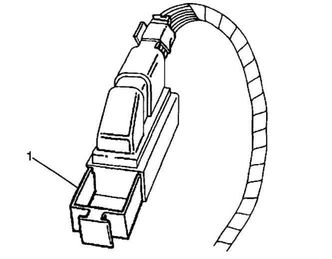
7. Disengage the locking tab (1) from the EBCM harness connector.
8. Disconnect the EBCM harness connector.
9. Remove any dirt/debris from the assembly.

imageOpen In New TabZoom/Print

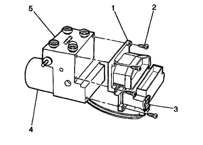
10. Remove the 6 EBCM to BPMV retaining bolt/screws.

Important: Do not pry apart using a tool. Be careful not to damage BPMV surface.

Important: Care must be taken not to damage the solenoid valves when the EBCM is removed from the BPMV.

11. Separate the EBCM (1) from the BPMV (4) by gently pulling apart until separated.
12. Disconnect the pump motor connector (3) at the bottom of the EBCM.
Was this
answer
helpful?
Yes
No
Thursday, March 25th, 2021 AT 7:03 AM

Please login or register to post a reply.

Sponsored links