Fan clutch problem affecting transmission, code P0495

Tiny
STAMPNW
  • MEMBER
  • 2002 CHEVROLET TRAILBLAZER
  • 4.2L
  • 6 CYL
  • 4WD
  • AUTOMATIC
  • 66,000 MILES
Vehicle has had intermittent issues with loud fan noise that are now almost constant. Apparently the fan clutch is fully engaging and sounds like a jet taking off. In addition, it seems when it does this the shifting characteristics of the transmission change to almost like a passing gear or driving up a hill, with shift points at higher RPM. Since it's an electronic transmission I'm assuming there are a number of things that alter transmission operation including fan speed. Actually latched a fault code of P0495 the other day, which would be consistent with the problem I'm experiencing. Are my assumptions correct?
Saturday, June 29th, 2019 AT 8:42 PM

3 Replies

Tiny
JACOBANDNICKOLAS
  • MECHANIC
  • 108,718 POSTS
Welcome to 2CarPros.

The code indicates an issue with the cooling fan circuit, however, it shouldn't have anything to do with shift points.

Since you have a scanner, I am going to provide a flow chart to diagnose the problem. Take a look through this and let me know if it helps or if you have other questions. The two attached pictures are the flow charts.

__________________

DTC P0495

pic 1

Steps 1 - 8

pic 2

Steps 9 - 14

Circuit Description
The cooling fan relay sends a Pulse Width Modulation (PWM) signal (12-14 volts) to the cooling fan by the cooling fan clutch supply voltage circuit. The Powertrain Control Module (PCM) uses the PWM signal, which controls the speed of the cooling fan by controlling the position of the oil control valve inside the clutch. If the cooling fan RPM is to high when the PCM is commanding 0%, DTC P0495 will set.

Conditions for Running the DTC
The engine is running.
The system voltage is greater than 8.5 volts.
The Intake Air Temperature (IAT) is greater than -7°C (19°F).
Zero percent duty cycle is commanded, and the engine RPM has been over 1800 RPM for at least 120 seconds.

Conditions for Setting the DTC
Cooling fan RPM exceeds 1600 RPM for 81 seconds.

Action Taken When the DTC Sets
The PCM illuminates the Malfunction Indicator Lamp (MIL) during the second consecutive trip in which the diagnostic test has been run and failed.
The PCM will store the conditions as Freeze Frame/Failure Records data.

Conditions for Clearing the MIL/DTC
The PCM turns the MIL OFF after the third consecutive trip that the diagnostic procedure has run and passed.
Clear the DTC using the Clear DTC Information function of the scan tool.

Diagnostic Aids
An inline connector could cause an intermittent DTC. Ensure to test for poor connections and pin retention at all inline connectors.
If the condition is not present, refer to Testing for Intermittent and Poor Connections.
If DTCs P0495 and P0113 are set and the weather is cold, the cooling fan code may be false. Clear DTC P0495, and after an IAT repair, check if the DTC will reset.

Test Description
The numbers below refer to the step numbers on the diagnostic table.
2. This step ensures that the DTC has failed this ignition cycle. If the scan tool displays Passed, then the answer is No.
3. The cooling fan noise should increase as the cooling fan engages. It can take up to 2 minutes for full cooling fan engagement. If cooling fan is previously fully engaged, then there will not be a noticeable change in cooling fan noise. Compare noise to a known good vehicle. If fan noise is louder than the known good vehicle, then answer Yes.
4. In the previous step the cooling fan was fully engaged. This step tests to ensure that the cooling fan will disengage. A noticeable noise difference should be heard between a fully engaged cooling fan and a disengaged cooling fan. The cooling fan is completely disengaged when the excessive fan noise is not heard.
5. Tests the ability of the PCM to control the cooling fan speed. If answer to question is Yes, ensure to refer to all Diagnostic Aids.
6. Disconnecting the cooling fan and running the engine ensure that the cooling fan is not engaged. When rotating the cooling fan it should spin freely. If not then the cooling fan will not disengage.

Let me know if you need help and the outcome if you find the issue.

Take care,
Joe
Was this
answer
helpful?
Yes
No
+1
Saturday, June 29th, 2019 AT 9:17 PM
Tiny
STAMPNW
  • MEMBER
  • 3 POSTS
Thanks for the information! I don't actually have a full blown scanner; just one of those Bluetooth adapters and the TorqueLite app on my android phone. I can see a few items like coolant temperature, RPM, intake air temp, etc. But I can't see things like fuel pressure or Fan RPM. Maybe there's a better app? Maybe if I'm by an auto parts store I'll try to borrow their scanner and see what's up.

Net is that the fan gets noisy right around 2,000 RPM. Doesn't matter if engine has been running a short or long while. Also doesn't matter if connector at shroud is on or off. With engine off the blade will move, but with resistance. Not sure if that's spinning "freely" or not. Only got the P0495 once. Hasn't returned since cleared.

I also drive a manual vehicle, so I'm thinking the noise is fooling me into thinking shift pattern is changing. On closer inspection, it appears to be shifting normally.
Was this
answer
helpful?
Yes
No
Monday, July 1st, 2019 AT 4:17 PM
Tiny
JACOBANDNICKOLAS
  • MECHANIC
  • 108,718 POSTS
Welcome back:

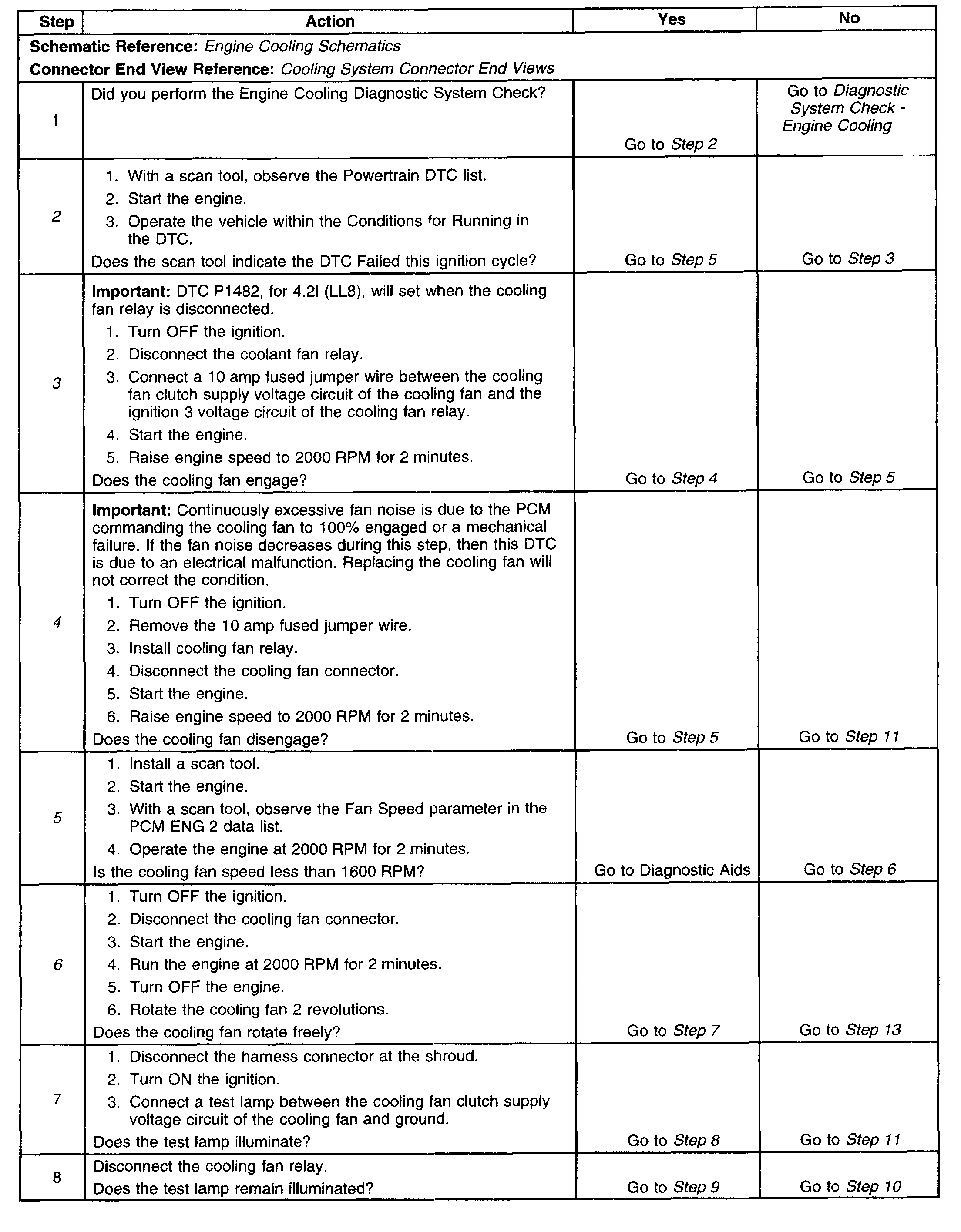
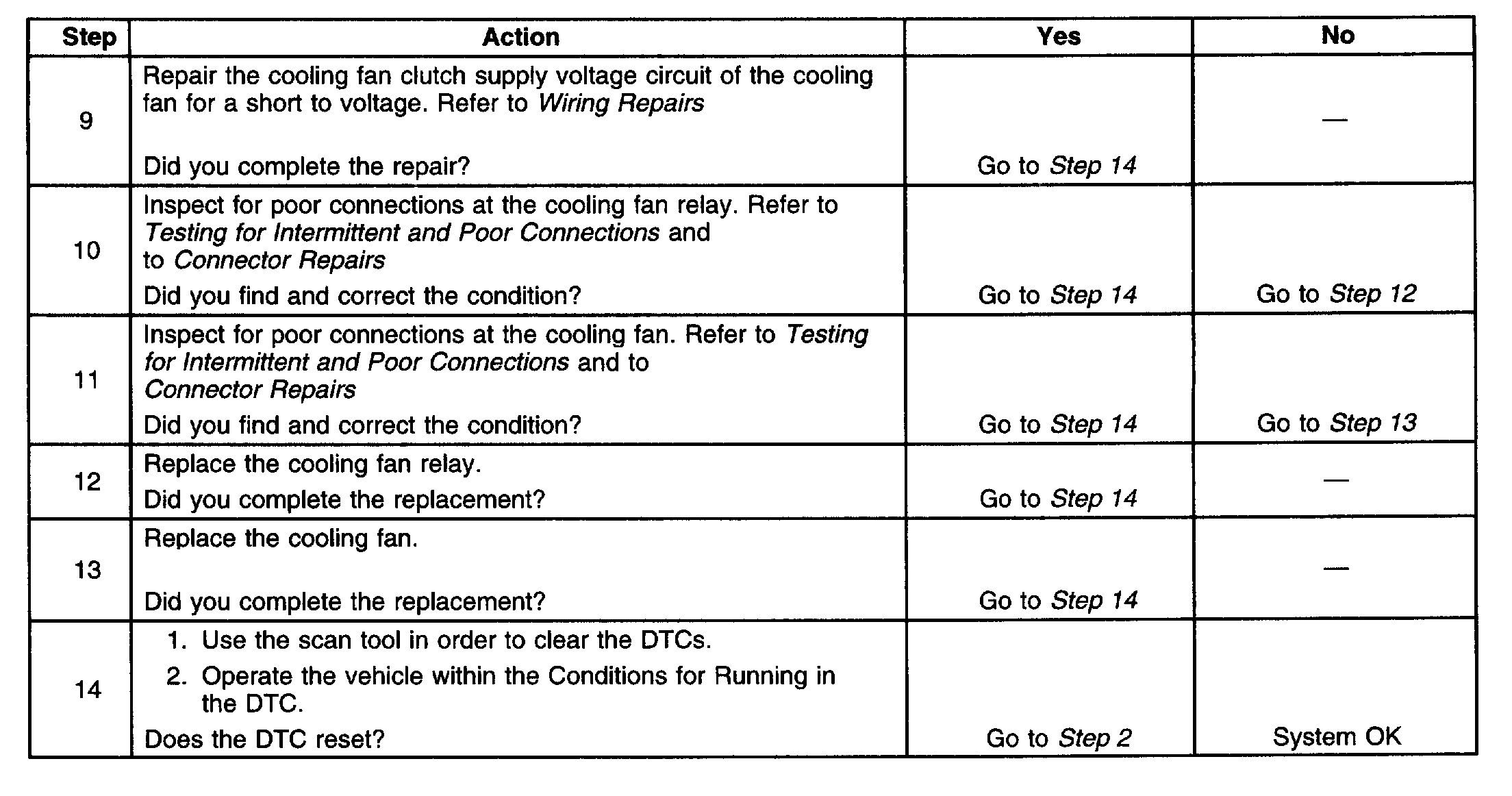
If it makes a lot of noise regardless of temperature and being disconnected or connected, it sounds like the clutch has failed and is staying engaged.

Here are a few links that you may find of interest. Take a look through them.

https://www.2carpros.com/articles/how-a-clutch-fan-works

https://www.2carpros.com/articles/fan-clutch-symptoms

https://www.2carpros.com/articles/fan-clutch-removal

If you determine that it is bad, here are the directions for replacement specific to your vehicle. The worst part is removing the fan shroud to get to it. All pics correlate with the directions,

++++++++++++++++++++++++++++++++++++++++++++++++++

COOLING FAN AND SHROUD REPLACEMENT
Cooling Fan and Shroud Replacement

- Tools Required
- J 38185 Hose Clamp Pliers
- J 46406 Fan Clutch Remover and Installer

Removal Procedure

pic 1

1. Remove the hood latch support.
2. Disconnect the transmission cooler lines at the engine and release the lines from the fan shroud.
3. Remove the 2 upper bolts on the fan shroud.
4. Drain the cooling system.
5. Reposition the upper inlet radiator hose clamp using J38185.
6. Remove the upper inlet radiator hose from the radiator.
7. Remove the electrical connector from the shroud.

pic 2

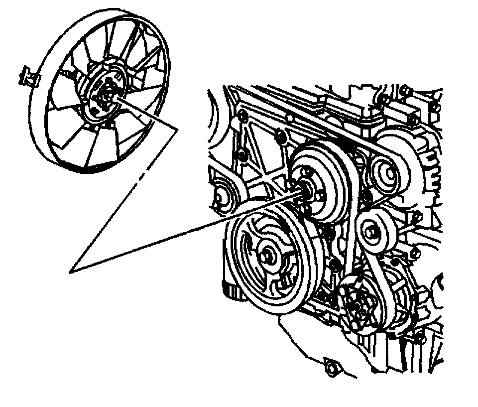
8. Position the water pump so the bolts are aligned in the vertical.
9. Remove the fan hub nut from the water pump shaft in a counterclockwise rotation. Using the J 46406, in order to secure the water pump pulley, loosen the cooling fan hub nut from the water pump shaft.
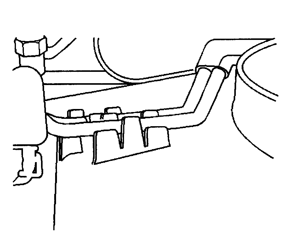
pic 3

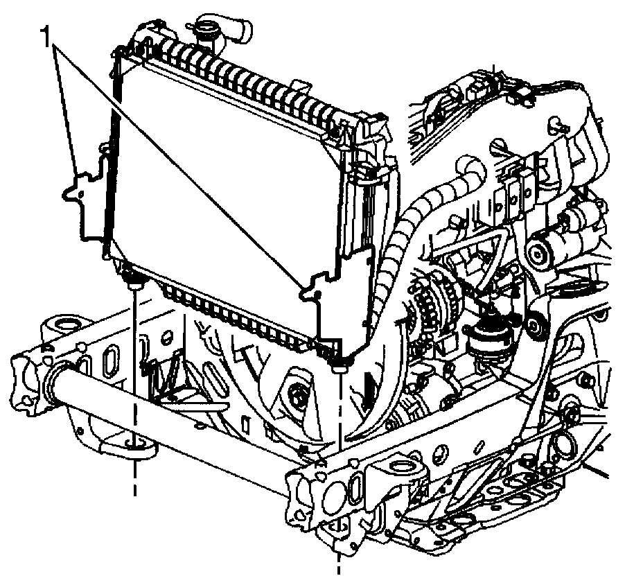
10. Unclip the fan shroud from the radiator at the side panels (1).
11. Tilt the radiator and the condenser forward.
12. Lift the fan and the shroud up and out towards the engine to release the fan from the radiator to clear the radiator inlet.

Installation Procedure

pic 4

1. Install the fan and the shroud onto the lip of the radiator bottom.

Notice: Refer to Fastener Notice in Service Precautions.

2. Install the 2 bolts into the upper fan shroud and tighten.
Tighten the bolts to 28 Nm (21 ft. lbs.).
3. Connect the electrical connector.
4. Clip the fan shroud to the radiator at the side panels (1).

pic 5

5. Using the J 46406 to secure the water pump pulley, install the fan nut to the water pump shaft in a clockwise rotation.
Tighten the fan hub nut to 56 Nm (41 ft. lbs.).

pic 6

6. Install the transmission cooler lines to the engine and clip into the fan shroud.
7. Install the hood latch support.
8. Install the upper inlet radiator hose to the radiator.
9. Reposition the upper inlet radiator hose clamp using J 38185.
10. Fill the cooling system.

__________________________________________________________

PROCEDURES
Fan Clutch Replacement

Removal Procedure

1. Remove the cooling fan and shroud. See: Fan Shroud > Procedures > Cooling Fan and Shroud Replacement
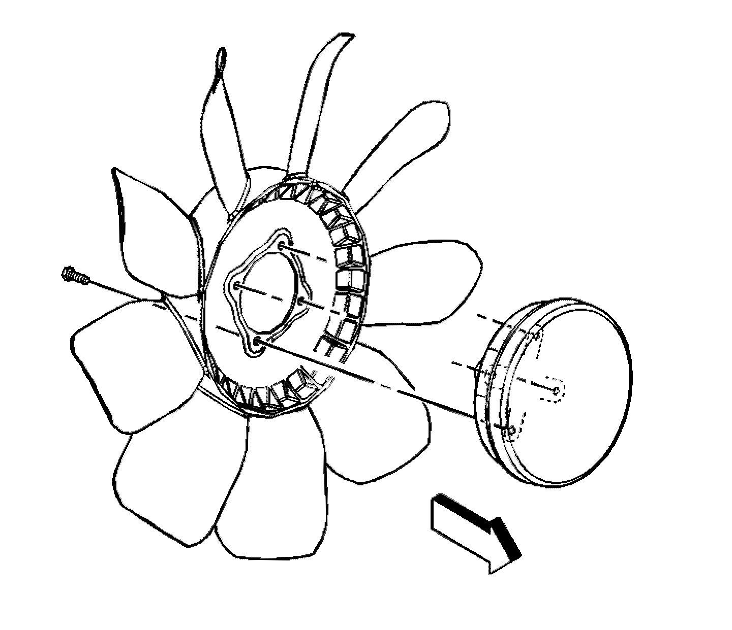
pic 7

2. Remove the fan clutch from the fan shroud.
3. Remove the bolts retaining the fan blade to the fan clutch.
4. Separate the fan blade from the fan clutch.

Installation Procedure

1. Assemble the fan blade to the fan clutch.

Notice: Use the correct fastener in the correct location. Replacement fasteners must be the correct part number for that application. Fasteners requiring replacement or fasteners requiring the use of thread locking compound or sealant are identified in the service procedure. Do not use paints, lubricants, or corrosion inhibitors on fasteners or fastener joint surfaces unless specified. These coatings affect fastener torque and joint clamping force and may damage the fastener. Use the correct tightening sequence and specifications when installing fasteners in order to avoid damage to parts and systems.

2. Install the 4 bolts to the fan blade. Tighten the bolts to 27 Nm (20 lb ft).
3. Install the fan clutch to the fan shroud.
4. Install the cooling fan and shroud. See: Fan Shroud > Procedures > Cooling Fan and Shroud Replacement

_________________________________

Let me know if this helps or if you have other questions.

Take care,
Joe
Was this
answer
helpful?
Yes
No
Monday, July 1st, 2019 AT 9:09 PM

Please login or register to post a reply.

Sponsored links