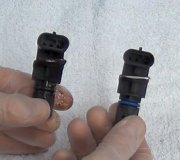
Here are the diagostic procedures.
DTC P0340: CAMSHAFT POSITION (CMP) SENSOR CIRCUIT MALFUNCTION
DTC Set Criteria
Engine speed is more than 50 RPM. Code will set if CMP sensor output voltage has not changed for 2 seconds.
Engine speed is more than 50 RPM. Code will set if normal cylinder
identification signal pattern has not been input for cylinder identification from CMP sensor and Crankshaft Position (CKP) sensor for 2 seconds.
Probable Causes
CMP sensor malfunction.
Open or short in CMP sensor circuit, or loose connector.
Engine Control Module/Powertrain Control Module (ECM/PCM) failed.
Diagnostic Procedures (2.4L)
1. Disconnect 3-pin CMP sensor connector. Turn ignition on. Check voltage between ground and CMP sensor connector terminal No. 3. If battery voltage exists, go to next step. If battery voltage does not exist, repair wiring between CMP sensor and MFI relay, then go to step 8.
2. Turn ignition off. Check resistance between ground and CMP sensor connector terminal No. 1. If resistance is less than one ohm, go to next step. If resistance is one ohm or more, repair wiring between ground and CMP sensor, then go to step 8.
3. Turn ignition on. Check voltage between ground and CMP sensor connector terminal No. 2. Voltage should be 4.8-5.2 volts. If voltage is as specified, go to next step. If voltage is not as specified, go to step 5.
4. Turn ignition off. Check CMP sensor connector. If problem exists, repair connector, then go to step 8. If problem does not exist, replace CMP sensor, then go to step 8.
5. Turn ignition off. Check ECM 22-pin connector C-38 or PCM 26-pin connector C-40. If problem exists, repair connector, then go to step
8. If problem does not exist, go to next step.
6. Check wiring between CMP sensor and ECM/PCM. If problem exists, repair appropriate wire, then go to step 8. If problem does not exist, go to next step.
7. Connect lab scope pick-up at CMP sensor or ECM/PCM. If connecting lab scope pick-up at CMP sensor, install Test Harness (MB991348) between CMP sensor connector halves. Connect pick-up lead to CMP sensor connector terminal No. 2. If connecting lab scope pick-up at ECM/PCM, connect pick-up lead to ECM connector C-38 terminal No. 88, or PCM connector C-40 terminal No. 56. Start engine and let idle. Compare waveform to a normal pattern. If waveform is normal, problem is intermittent. If waveform is not normal, replace ECM/PCM, then go to next step.
8. Using scan tool, clear DTCs. Test drive vehicle following OBD-II drive cycle other monitor pattern. Check for DTCs. Confirm DTC does not reset.
Friday, August 31st, 2012 AT 6:53 PM


