TEST C
Ensure good connection at generator 3-pin electrical connector. Repair as necessary and check system operation. If connection is okay, go to next step.
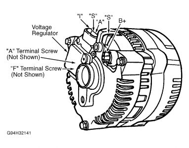
With engine at 2000 RPM, measure voltage between generator terminal B+, Black/Orange wire (Yellow/White wire on F250 Super-Duty and F350 Pickups) and ground. See Fig. 1 . If voltage is less than 16 volts, go to next step. If voltage is 16 volts or more, go to TEST G .
With engine running at 2000 RPM, measure voltage between generator 1-pin connector terminal "S" (White/Black wire) and ground. See Fig. 1 . If voltage is 5 volts or greater, go to next step. If voltage is less than 5 volts, replace voltage regulator. See VOLTAGE REGULATOR under REMOVAL & INSTALLATION.
Turn ignition off. Disconnect generator 1-pin connector terminal "S" (White/Black wire). See Fig. 1 . Start vehicle. With engine running, measure voltage between generator terminal "S" and ground. If voltage is 5 volts or greater, repair White/Black wire between generator 1-pin connector and generator 3-pin connector. See WIRING DIAGRAMS . If voltage is less than 5 volts, replace generator. See GENERATOR under REMOVAL & INSTALLATION.
TEST G
Turn ignition to run and measure voltage drop in voltage sensing circuit "A" by connecting voltmeter positive lead to battery positive terminal. Connect voltmeter negative lead to generator terminal "A" screw. See Fig. 3 . If voltage is less than .5 volt, go to next step. If voltage is .5 volt or greater, voltage drop is excessive. Repair circuit "A" and check system operation. See WIRING DIAGRAMS .
Start engine and turn off all accessories. Increase engine speed while measuring voltage between battery terminals. If battery voltage stays at or less than 15 volts, go to next step. If battery voltage increases to greater than 15 volts, go to step 6 .
Turn ignition off. Measure voltage between generator terminal "F" screw and ground. See Fig. 3 . If battery voltage is present, go to step 5 . If battery voltage is not present, go to next step.
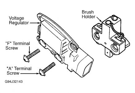
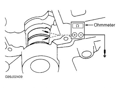
Disconnect generator 3-pin and 1-pin connectors. Remove voltage regulator and brush holder. See VOLTAGE REGULATOR under REMOVAL & INSTALLATION. Measure resistance between each generator slip ring and ground. See Fig. 4 . If resistance is greater than 1000 ohms between both slip rings and ground, replace voltage regulator. If resistance between one or both slip rings and ground is less than 1000 ohms, replace generator. See GENERATOR under REMOVAL & INSTALLATION.
Start engine. Measure battery voltage and observe charge indicator while increasing engine speed. If battery voltage increases to greater than 15 volts, or indicator light flickers, repair "A" or "I" circuits from generator. See WIRING DIAGRAMS . If battery voltage is 15 volts or less and indicator light does not flicker, replace generator. See GENERATOR under REMOVAL & INSTALLATION.
Measure voltage between generator terminal "F" screw and ground while increasing engine speed. If voltage increases with engine speed, replace generator. See GENERATOR under REMOVAL & INSTALLATION. If voltage does not increase with engine speed, replace voltage regulator. See VOLTAGE REGULATOR under REMOVAL & INSTALLATION.


Wednesday, January 20th, 2021 AT 6:48 PM
(Merged)


