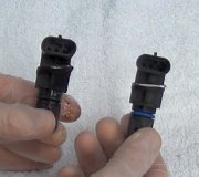
1. Turn ignition off. Disconnect Camshaft Position (CMP) sensor connector. CMP sensor is located on end of cylinder head. Go to next step.
2. Turn ignition on. Using scan tool in voltmeter mode, check voltage on CMP sensor connector (harness side) 8-volt supply circuit. See CMP SENSOR CONNECTOR WIRE IDENTIFICATION table.
CMP SENSOR CONNECTOR WIRE IDENTIFICATION
Application Wire Color
CMP 8-Volt Supply Circuit Orange
CMP Signal Circuit Tan/Yellow
CMP Ground Circuit Black/Light Blue
3. If voltage is more than 7 volts, go to next step. If voltage is 7 volts or less, repair 8-volt supply circuit. See CMP SENSOR CONNECTOR WIRE IDENTIFICATION table.
4. Turn ignition off. Connect a jumper wire to CMP sensor signal circuit. See CMP SENSOR CONNECTOR WIRE IDENTIFICATION table. Turn ignition on. Using scan tool, note CMP sensor signal state. While observing scan tool display, tap other end of jumper wire to CMP sensor ground circuit. See CMP SENSOR CONNECTOR WIRE IDENTIFICATION table.
5. If a CMP signal is detected, replace CMP sensor. Perform TEST VER-2A. If a CMP signal is not detected, turn ignition off. Using scan tool in ohmmeter mode, check resistance of CMP sensor ground circuit. See CMP SENSOR CONNECTOR WIRE IDENTIFICATION table. If resistance is 5 ohms or less, go to next step. If resistance is more than 5 ohms, repair open CMP sensor ground circuit. Perform TEST VER-2A.
6. Disconnect Powertrain Control Module (PCM) connectors. Using an external ohmmeter, check resistance of CMP signal circuit between CMP sensor connector and PCM connector. See CMP SENSOR CONNECTOR WIRE IDENTIFICATION table and POWERTRAIN CONTROL MODULE WIRE IDENTIFICATION table. If resistance is less than 5 ohms, go to next step. If resistance is more than 5 ohms, repair open CMP signal circuit. See CMP SENSOR CONNECTOR WIRE IDENTIFICATION table. Perform TEST VER-2A.
PCM TERMINAL 33 WIRE IDENTIFICATION
Application Wire Color
PCM Terminal No. 33 (Camshaft Position Sensor Signal Circuit) Tan/Yellow
7. Using scan tool in ohmmeter mode, check resistance of CMP signal circuit. See CMP SENSOR CONNECTOR WIRE IDENTIFICATION table. If resistance is 5 ohms or less, repair short to ground in CMP signal circuit. See CMP SENSOR CONNECTOR WIRE IDENTIFICATION table. Perform TEST VER-2A. If resistance is more than 5 ohms, replace PCM. Perform TEST VER-2A.
Friday, August 14th, 2015 AT 11:51 AM


