94' Saturn SL

Tiny
SATURNMAN
  • MEMBER
  • 1994 SATURN
  • 4 CYL
  • FWD
  • MANUAL
Where is the Coolant Temp Sensor located on the motor?

My plan is to find it. Then OHM out the harness. I'm guessing it has two wires feeding the sensor and 1 wire should have a decent ohm reading to ground and the other wire should be the signal wire correct? With no continuity to ground? CODE 15 is set. Check engine light is on. I used a jumper wire at the Diagnostic connector jumping pin A and B to read this code. I thought to check the harness prior to swapping out the sensor would be wise. Am I on the right track? Mitchell
Thursday, March 17th, 2011 AT 9:28 PM

5 Replies

Tiny
RASMATAZ
  • MECHANIC
  • 75,992 POSTS
Use an ohmmeter/DVOM or Analog -Read the resistances of the CTS hot/cold, if its not within specs replace it-
Was this
answer
helpful?
Yes
No
+1
Thursday, March 17th, 2011 AT 9:32 PM
Tiny
WRENCHTECH
  • MECHANIC
  • 20,761 POSTS
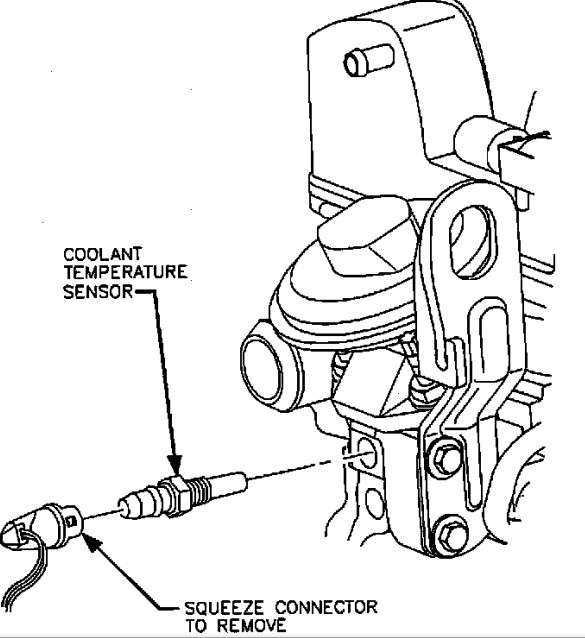
Here's a picture of the location
Was this
answer
helpful?
Yes
No
+1
Thursday, March 17th, 2011 AT 10:01 PM
Tiny
SATURNTECH9
  • MECHANIC
  • 30,869 POSTS
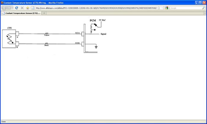
Just to add to this one your car has two sensor's the bottom one with the two wires is your coolant temp sensor that tells the computer what temp the engine is. There is a black wire which is grounded at the computer and the yellow wire is the 5 volt feed from the computer. Also inspect the connector to the sensor if it's corroded it will have to be replaced. Most of the time it's just a bad sensor pretty common on those car's. But I would also check the wires also.
Was this
answer
helpful?
Yes
No
Thursday, March 17th, 2011 AT 10:36 PM
Tiny
SATURNMAN
  • MEMBER
  • 2 POSTS
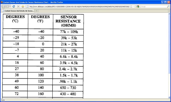
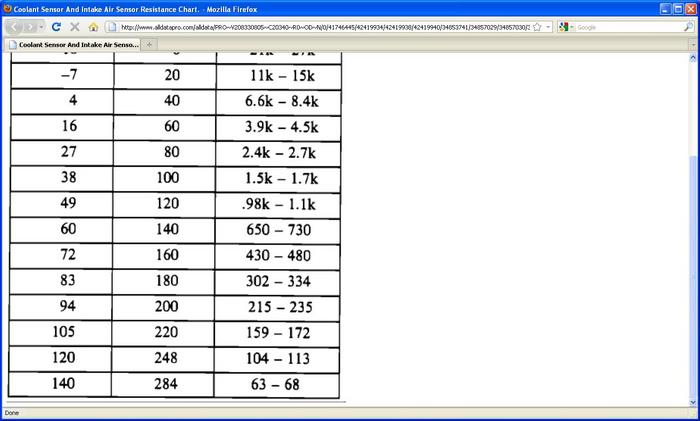
Awesome thanks. So. What would the resistance be across the pins? Or should it be of the sensor? It was a plastic tiped sensor. I ohmed out the harness. I was disapointed to see both wires had continuity to ground. Across my sensor pins I had 41 ohms.
Was this
answer
helpful?
Yes
No
Thursday, March 17th, 2011 AT 11:14 PM
Tiny
SATURNTECH9
  • MECHANIC
  • 30,869 POSTS
The black wire on the connector is ground the yellow wire is 5 volt's you can see that in the wire diagram I posted.I have posted all the info you will need to trouble shoot your problem let me know what you find.

DESCRIPTION

The coolant temperature sensor (CTS) is a thermistor located in a coolant passage. When coolant temperature is cold the sensor has a high resistance, as temperature increases the resistance of the sensor decreases. The PCM provides a five volt signal to the coolant sensor, which is also connected to PCM ground. The PCM reads the voltage drop on the signal line to determine coolant temperature.

CODE PARAMETERS

Code 15 will set if:

* The CTS reads below -35°C (-31°F).
* The engine has been running longer than five minutes with a temperature less than -35°C (-31°F).

DIAGNOSTIC AIDS

* Refer to Temperature vs. Resistance Chart.
* When attempting to diagnose an intermittent problem, use the Scan Tool to review supplemental diagnostic information. The supplemental data can be used to duplicate a problem. Select MALF History from Scan Tool EC menu.
* Check the tightness of the female terminal grip with a spare male terminal.
* Start engine and observe CTS reading on Scan Tool.
* Normal operation is for the CTS to rise smoothly to approx. 88°C (190°F) (thermostat opens) then stabilize.
* Visually inspect CTS wires for damage. Wiggle wires while observing scan tool CTS reading and watch for a sudden shift in temperature.
* CTS may be compared to ATS temperature, with a Scan Tool if engine has cooled overnight at ambient temperature. They should be within four degrees of each other with ignition On - engine Off
Was this
answer
helpful?
Yes
No
Friday, March 18th, 2011 AT 2:37 AM
Please login or register to post a reply.

Sponsored links