Yup. My memory is fuzzy on the location, but the voltage regulator is in the SMEC, (single module engine controller).
The second set of readings does indeed suggest the voltage regulator could be intermittently open, but a bad connection in a wiring connector would be more common. Also, you're one step ahead of the diagnosis by finding one of the two smaller alternator terminals having a lower voltage than the other. If you look at the first set of readings where you had 14.04 volts, that's the feed. That one you leave alone from now on. The other one, being lower, is going to the voltage regulator and is the one to do the testing on.
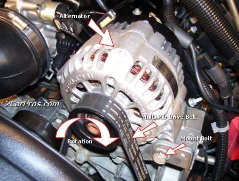
With a break in the wire going to the regulator, you will normally see exactly the same voltage on both small terminals. I have a trick to figure out which one is connected to the regulator. You can't tell by the wire colors because they both go through a small black plastic block that the terminals are molded to. There's no easy way to know which wire goes to which terminal, ... Unless you know my wondrous trick.
What you want to see is a difference in voltage between those two small terminals. The greater the voltage difference, the stronger electromagnetic field the field winding is making and the more output you'll get. In your first readings that difference is 2.7 volts which is about typical for running the fuel pump, ignition system, and radio. Maybe even the head lights. In the second set of readings there's only a quarter volt difference. The terminal with 11.58 volts is down from 14.04 because the system voltage is down. At issue here is both terminals are essentially the same. That means almost no magnetic field is being developed, so no output will be developed.
Also, we know the brushes inside the alternator are okay. The most common failure is worn brushes making intermittent contact. That can go on for months before the failure becomes permanent. When that happens you'll find 0.00 volts on the second small terminal.
To prove everything else in the output circuit is working, use a piece of wire or a clip lead to ground that second small terminal that had the 11.34 volts. Do that just long enough to verify everything works. If you monitor battery voltage or turn on the head lights, you'll see the charging voltage go way up to more than 15.0 volts. Don't raise engine speed because that can send the voltage to more than 20.0 volts and cause damage. And PLEASE do not ever disconnect the battery while an engine is running. I did that every year on the alternator test bench to prove to my students what will happen. The voltage regulator needs the battery in the circuit to help it do its job. It is real easy without the battery, and by raising engine speed, to hit well over 30.0 volts. That will damage computers, the radio, and any bulbs that are turned on.
Once you momentarily ground that terminal and see system voltage go up, we'll know everything else is working. You'll hear the alternator strain too, and the head lights will get bright. The next step is to ground that same circuit in a connector further down the line, but I'm going to have to find a wiring diagram to see where that is. That's going to tell us if that piece of wire is okay. This was usually a dark green wire but I'll be back shortly with more information.
Saturday, May 23rd, 2015 AT 4:29 PM


