When shifting out of park the locks intermittently do not automatically lock?

Tiny
G6PONTIACWI
  • MEMBER
  • 2006 PONTIAC G6
  • V6
  • 2WD
  • AUTOMATIC
  • 200,000 MILES
When I take the car out of park the locks won't always automatically lock like they should, I can still lock them by pressing the button on the door. If they don't lock automatically the car won't shift at all. If they do lock automatically, it will usually shift with no issues, but sometimes it won't. Also, the locks rarely unlock when putting the car back into park. Someone else recently drove the car and said the locks kept locking and unlocking by themselves while they were driving. I haven't witnessed that myself. I hooked up a code reader but no codes are popping up.
Tuesday, July 2nd, 2024 AT 11:36 PM

23 Replies

Tiny
AL514
  • MECHANIC
  • 4,688 POSTS
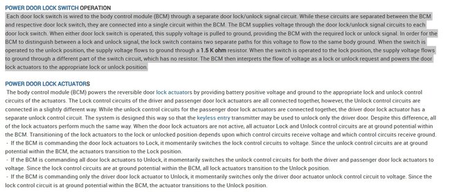
Hello, this is an interesting case, looking through service info on Lock operations according to the shift position, there are 4 programmable modes, obviously it is set to Lock/unlock per Park or out of Park, but since this seems to be an intermittent issue that actually effects the vehicle shifting, it sounds like possibly a faulting module or network issue because these functions concern multiple modules.
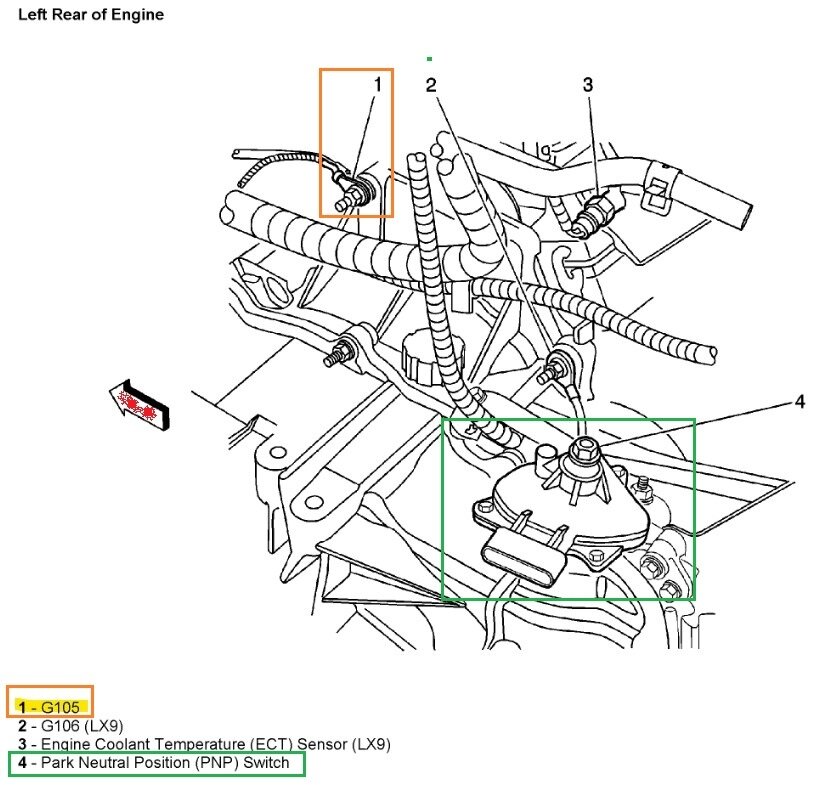
Just to be sure of this Ground for the transmission range switch, G105, it is located on the Driver side rear of the engine compartment on a transmission stud below the upper coolant hose (black wire with white stripe) see if the ground looks corroded. And if you have a test light, hook it to battery positive and touch that ground location to see if it lights the test light. I'll grab some diagrams for you. But the command to lock all 4 doors at once has to come from the BCM directly, Ill post that diagram as well.

The shifting might be the transmission not seeing that its actually in Drive, does your scan tool have the capability of scanning other modules besides the ECM? And do you have a multimeter?
Was this
answer
helpful?
Yes
No
Wednesday, July 3rd, 2024 AT 1:14 PM
Tiny
G6PONTIACWI
  • MEMBER
  • 10 POSTS
I'm not home at the moment, but I'm not sure if the scan tool has the capability of scanning other modules than the ECM or not. I do have a multimeter.
Was this
answer
helpful?
Yes
No
Wednesday, July 3rd, 2024 AT 1:43 PM
Tiny
AL514
  • MECHANIC
  • 4,688 POSTS
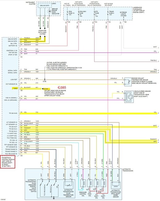
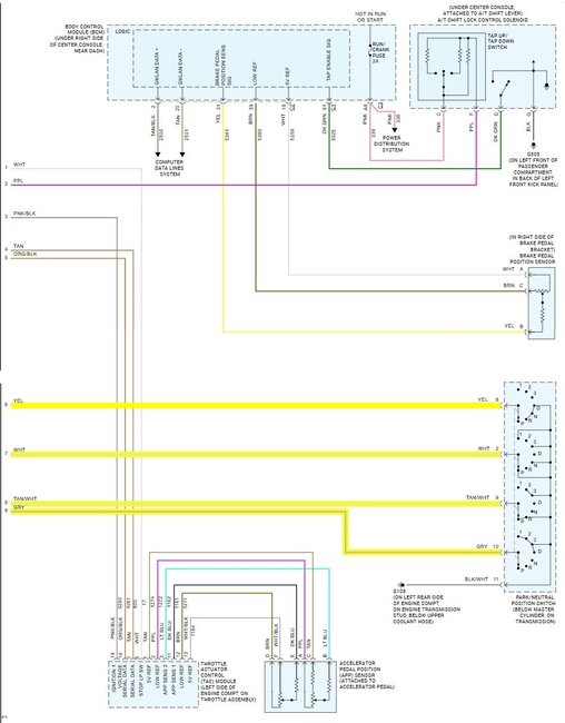
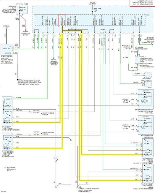
Okay, well this is the one output command to lock all 4 doors from the BCM, all 4 door locks are on one circuit internal to the BCM. The highlighted wires are just the lock wires to each door. Diagram 2 is the BCM's door lock operations. Diagrams 3, 4 are the PCM to the transmission Range switch, which is a pull-down circuit, it grounds certain wires to tell the PCM which gear you have it shifted in. Thats why I mentioned G105, its the only Ground for the Range switch, so with the engine running set your meter on DC volts and check from battery negative to G105 in diagram 5, looking at the engine from the front the ground should be on your right side. You should have as close to 0volts as possible when voltage drop testing the Ground to battery negative. Next turn the key off and check the Park Neutral Position Switch (PNP) connector for any corrosion inside the connector pins. Thats the Range switch.
G105 is also the only PCM ground, so I would take the nut off the stud and at least clean that ground really well. Even possibly run another wire from it to battery negative just to reinforce it the ground.
You may find additional codes stored in other modules if you take it somewhere that can do a full system scan on the entire vehicle. Body control module codes won't show up in the PCM because they don't effect emissions components. So I recommend getting a full system scan.
Was this
answer
helpful?
Yes
No
Wednesday, July 3rd, 2024 AT 2:30 PM
Tiny
AL514
  • MECHANIC
  • 4,688 POSTS
O' Reilly's, AutoZone, Advanced Auto, etc, might be able to do a full system scan for free.
Was this
answer
helpful?
Yes
No
Wednesday, July 3rd, 2024 AT 2:33 PM
Tiny
G6PONTIACWI
  • MEMBER
  • 10 POSTS
Thank you for your responses, you've given me a lot of things to check out. I'll be pretty busy the next couple days, but I'll try to get it all tested and bring it somewhere for a scan. Maybe it's because I'm on my phone but I don't see any of the diagrams you're talking about. I'll check on a computer when I get home. Thanks again for all your help!
Was this
answer
helpful?
Yes
No
Wednesday, July 3rd, 2024 AT 3:33 PM
Tiny
AL514
  • MECHANIC
  • 4,688 POSTS
Hmm okay, well, here are all the diagrams again, its best if you are on a larger screen to see these, I'm not sure what happened, but they are all missing from my other posts. But the 3rd diagram is the transmission range switch and G105, hopefully you can see these. Let me know.
Was this
answer
helpful?
Yes
No
Wednesday, July 3rd, 2024 AT 3:51 PM
Tiny
G6PONTIACWI
  • MEMBER
  • 10 POSTS
I can see them all now. Thanks again!
Was this
answer
helpful?
Yes
No
Wednesday, July 3rd, 2024 AT 4:05 PM
Tiny
AL514
  • MECHANIC
  • 4,688 POSTS
Okay, let us know what you find, using a test light to check that Ground location will put a little bit of a load on it, or you could use a head lamp bulb and use the stud G105 is grounded to as the ground for a head light bulb. Those pull around 4amps, just don't keep it hooked up long, they get hot real fast. If you find corrosion in any electrical connectors there's terminal spray you can buy that will help clean out connectors/pins unless you end replacing connectors.
Was this
answer
helpful?
Yes
No
Thursday, July 4th, 2024 AT 12:13 PM
Tiny
G6PONTIACWI
  • MEMBER
  • 10 POSTS
I checked the grounds, and cleaned them up, it looked good. And was able to get a scan and the code P0705 popped up. It says transmission range sensor circuit.
Was this
answer
helpful?
Yes
No
Saturday, July 6th, 2024 AT 11:40 AM
Tiny
AL514
  • MECHANIC
  • 4,688 POSTS
Did you disconnect the Range switch ay any point?
Was this
answer
helpful?
Yes
No
Saturday, July 6th, 2024 AT 12:10 PM
Tiny
G6PONTIACWI
  • MEMBER
  • 10 POSTS
I wasn't able to get the connector off earlier to check if there was any corrosion on the pins. I'm going to work on that again and I'll let you know how it looks.
Was this
answer
helpful?
Yes
No
Saturday, July 6th, 2024 AT 12:49 PM
Tiny
G6PONTIACWI
  • MEMBER
  • 10 POSTS
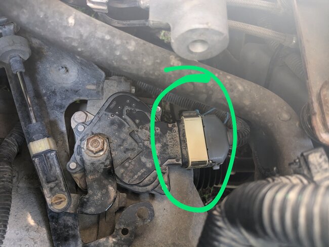
And this picture is what I'm supposed to be checking, correct?
Was this
answer
helpful?
Yes
No
Saturday, July 6th, 2024 AT 1:05 PM
Tiny
AL514
  • MECHANIC
  • 4,688 POSTS
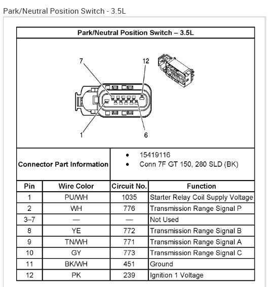
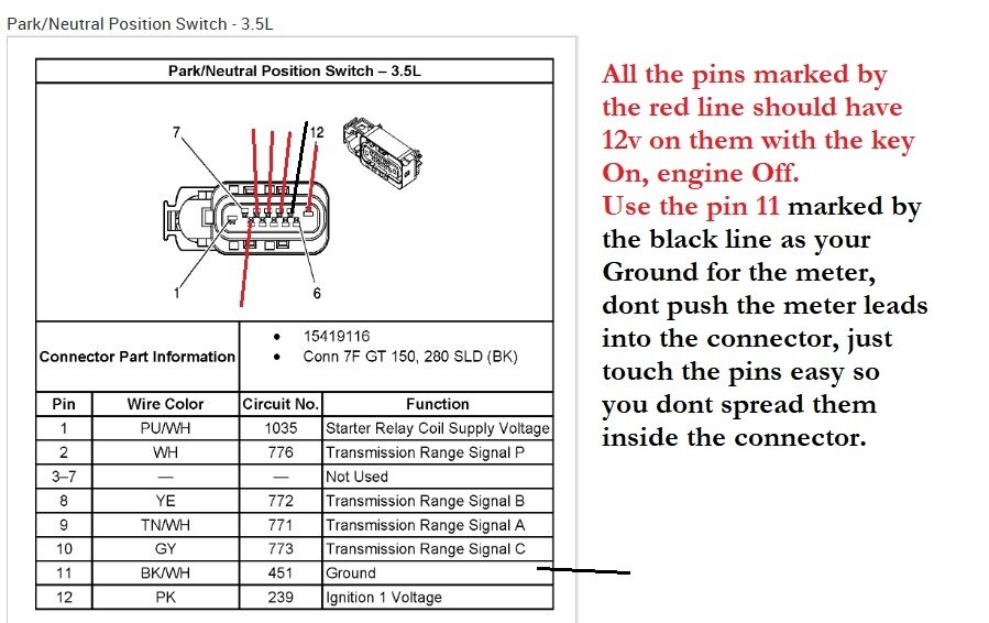
This is the Range switch OEM wiring, this would explain part of the issues you're having, you'll notice on all 4 of these Signal wires there's a small square symbol, that's a resistor where each wire sends 12-volts down to the Range switch and as you shift into Park for example, it causes the wires marked A and P to be pulled to Ground, and wires B and C are not, so the PCM reads 0-volts on pins A and P and 12volts on pins B and C. Thats one of the combinations the PCM is looking for depending on what position the shifter is in, and the code P0705 is showing that one of those combinations is incorrect and the PCM is seeing the incorrect voltage on one of the four pins. If that makes sense.
So, I would check each of the 4 wires at the Range switch for 12-volts, they should all have that voltage with the connector unplugged with the Key On, if any are missing it write down which wire it is. A is tan/white wire, B is a yellow wire, C is a grey wire, and P is a white wire.
Was this
answer
helpful?
Yes
No
Saturday, July 6th, 2024 AT 1:06 PM
Tiny
AL514
  • MECHANIC
  • 4,688 POSTS
Correct, refresh this page, I posted the first test instructions in my last post.
Was this
answer
helpful?
Yes
No
Saturday, July 6th, 2024 AT 1:07 PM
Tiny
AL514
  • MECHANIC
  • 4,688 POSTS
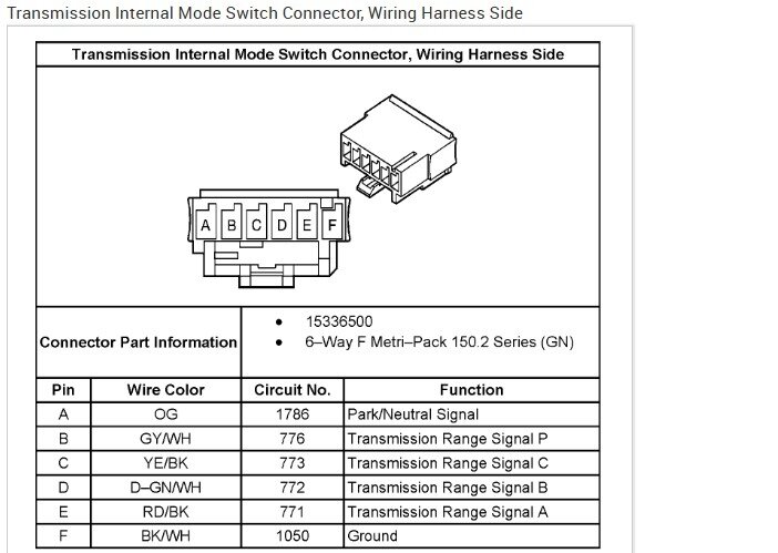
There are 2 different transmissions for this vehicle, one had a 6 wire range switch and the other has a 12 pin connector, the diagram of the connector I posted is for the 12 pin connector type, you see the 6 wire connector has different wire colors, so let me know which connector you have, you should be able to see when you unplug it.
Was this
answer
helpful?
Yes
No
Saturday, July 6th, 2024 AT 1:16 PM
Tiny
G6PONTIACWI
  • MEMBER
  • 10 POSTS
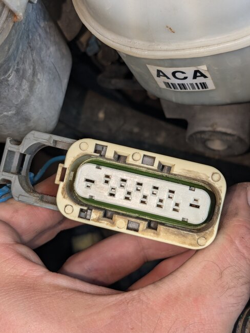
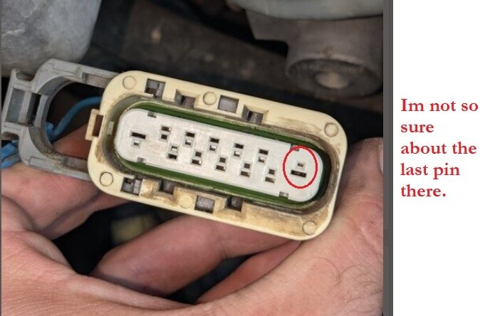
Here it is.
Was this
answer
helpful?
Yes
No
Saturday, July 6th, 2024 AT 1:21 PM
Tiny
AL514
  • MECHANIC
  • 4,688 POSTS
Okay, here's your testing, just touch the meter pins to the connector pins lightly, you don't want to spread the pins inside the connector, or they will never make good contact ever again, do you see any corrosion or spread pins inside there? I don't, but it's difficult to see from the picture.
Was this
answer
helpful?
Yes
No
Saturday, July 6th, 2024 AT 1:33 PM
Tiny
AL514
  • MECHANIC
  • 4,688 POSTS
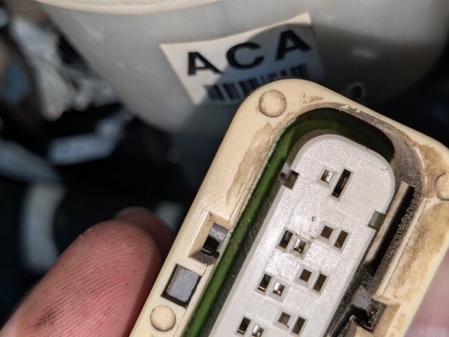
I'm not too sure about pin 12 there, is the pin pushed in or spread there?
Was this
answer
helpful?
Yes
No
Saturday, July 6th, 2024 AT 1:37 PM
Tiny
G6PONTIACWI
  • MEMBER
  • 10 POSTS
I can't see any spread pins or corrosion. Testing all the pins I'm only getting 10.98 volts except for 12 I'm getting 11.56.
Was this
answer
helpful?
Yes
No
Saturday, July 6th, 2024 AT 1:48 PM
Tiny
G6PONTIACWI
  • MEMBER
  • 10 POSTS
Here's a better picture of 12 hopefully.
Was this
answer
helpful?
Yes
No
Saturday, July 6th, 2024 AT 1:51 PM

Please login or register to post a reply.

Sponsored links