For the alignment question, there is no longer such a thing as a two-wheel alignment. If you get charged for that, what that means is they just aligned the two front wheels to the frame and truck centerline, like they did back in the fifties through the 1980s. Today every shop uses a very expensive alignment computer that looks at the direction the rear wheels are steering, then has you adjust the front wheels to them to make all four of them parallel to each other, regardless which way the rear wheels are steering off to one side. That ensures you end up with a straight steering wheel. Every vehicle, including brand new ones, have a little rear "thrust angle". That makes the rear steer to one side, even if it's just a little. If the front wheels aren't adjusted to compensate for that, you'll have to do that by turning the steering wheel to one side a little. Even if you request a two-wheel alignment, or are offered one, projectors get installed on all four wheels, otherwise the front projectors won't have any targets to look at.
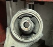
As for the bolts, can you post a photo of them? It is well-known that Ford and GM can't be bothered to provide alignment adjustments from the factory. With GM cars, the lower of the two lower strut mounting bolt holes must be made into ovals by grinding them with a die grinder the first time one needs to be adjusted. On a lot of Ford models, there's no way to correct some alignment adjustments. With GM trucks, square factory-installed blocks must be removed and discarded the first time an adjustment is needed, then a special punch-out tool is needed to make the mounting hole elongated. At that point the pivot bolt is replaced with a cam bolt to make the adjusting easier. It sounds like that's what you might have found on the right rear. A cam bolt has a larger, off-center head that looks like a giant washer, but it rotates as the bolt head is rotated. That forces the bolt to move sideways. It takes that corner of the control arm with it to change, or adjust its position.
Ford actually had a nice idea in the late '90s on some of their truck models. That was to use a two-piece upper control arm on the right side. Each upper control arm is a triangle with the upper ball joint at one of its points. The other two are those pivot bolts. By sliding both adjustments in or out, you move the upper ball joint away from or closer to the center of the truck. That's the "camber" adjustment and has the biggest affect on tire wear patterns. If you move one corner of the control arm in and the other one out, you move the ball joint forward or rearward. That's the "caster" adjustment.
Positive camber is when the top of the wheel tilts out on top. Tires want to roll in the direction they're leaning, so besides being in specs for best tire wear, it's important camber is the same on both sides so their pulls offset each other.
Caster has to be visualized, but think about how the fork of a bicycle is tilted rearward at the top. That's what allows you to ride no-handed as long as there's weight on the bicycle. Caster has very little affect on tire wear but it does cause a pull. Positive caster is when the upper ball joint is further to the rear than the lower one. When the vehicle's weight is put on a wheel, positive caster makes that wheel want to turn toward the center of the truck. Ideally the other wheel wants to do the same thing. When the steering linkage is connected between the two wheels, those caster pulls offset each other and the truck goes straight.
This leads to those adjustments. It's pretty easy to set camber in specs on the first wheel. For caster, the range of allowable specs is pretty broad, so we can take what we end up with, within reason. The problem comes when we move on to the second wheel. It's still rather easy to set camber where we want it, but now instead of being satisfied with whatever we get for caster, we have to take a lot more time and frustration getting caster to match that on the first wheel. When they don't, we pick the one wheel that's furthest from "perfect" and readjust that one. This can go on for a long time, running back and forth between wheels until we give up and hope it's close enough. If we end up with a little camber pull to one side, it can be offset by exactly twice as much caster pull the other way. Both are measured in degrees and tenths or hundredths of a degree. For camber, for example, 0.00 degrees means that wheel is perfectly straight up and down, as viewed from in front of the truck. 90.00 degrees would mean the wheel is laying flat on its side. A typical camber setting for most trucks would be in the order of 0.50 degrees, not enough tilt to see by eye. If you end up with a difference, side-to-side, of 0.25 degrees camber pull to the left, it would be offset by 0.50 degrees caster pull to the right.
The problem, as I mentioned, is getting those four readings to be in specs and to not cause a pull. That is often very frustrating and time-consuming. One way to address that is to set the alignment computer to read to only tenths of a degree after the decimal point. Numbers get rounded off and are easier to make them look good on the computer screen. I always set my computers to read to the hundredth of a degree. The extra precision forced me to set each adjustment with more accuracy. It took longer but I had a much better chance of having a happy customer.
Ford had a nice idea to address that difficulty in making the adjustments match. The left wheel was set to put camber in specs, and to get caster as close to perfect as possible, then it could be left alone. On the right side, all that was needed was to set camber again, which is easy to do when you don't have to worry where caster ends up. Once camber was set by using those two pivot bolts, caster had a secondary adjustment provision in the two-piece upper control arm. The outer half was bolted to the inner half. When those bolts were loosened, the outer half could be slid forward or rearward to adjust caster without affecting camber. That was an excellent idea, but it has a major drawback. That is Ford intended that design to make it faster to adjust the alignment on the assembly line. The upper ball joint is cast as part of that control arm, and when it needs to be replaced, you can't buy that design. All that is available is the standard one-piece design. At that point you're back to the same frustrations this design has always had.
Another problem has to do with chassis ride height. This is a problem caused by age, not mileage. The springs sag with age, and that changes the arcs and motions the steering and suspension parts go through as the truck bounces up and down. Camber and caster can still be adjusted to look good on the computer screen, but those numbers only pertain to a vehicle that's standing still. Ford leads the world in manufacturers with miserable tire wear. The Ranger and down-sized Bronco have the worst tire wear except for the Tempos and '80s Ford-built Escorts. Only the four-wheel-drive Ranger has worse tire wear. All of these are seriously affected by incorrect ride height. As evidence of that, watch what happens to the front wheels when those 4wd trucks are raised on a hoist. Those are the motions the tires go through as the trucks bounce up and down as they go down the road. The best you can do to reduce that wear is to keep the chassis ride height correct. That involves replacing weak coil springs on the front. Rear tire wear with the solid rear axle doesn't have this problem. The vehicles affected by this use the "twin I-beam" front suspension. The one huge advantage to the I-beam axle is it's very strong. The biggest disadvantage is poor ride quality so it's used only on trucks. The twin I-beam is a compromise of both designs. It's quite strong and it rides better than the single I-beam axle, but it has the worst tire wear of all the suspension designs.
The two-wheel-drive Ranger uses the upper and lower control arms, also called the "long arm / short arm", (SLA) suspension. It offers the best ride quality because road forces have to change directions multiple times, so they get absorbed, before they reach the passenger compartment. It also offers the best tire wear. When you look at the two control arms, you'll see the lower one is longer and should be parallel to the ground. The upper one is shorter and is angled downward at the ball joint. That makes the two of them go through wildly different arcs as the truck bounces up and down. That makes the wheel and tire tip back and forth rather than slide back and forth across the road surface. Besides being time-consuming to adjust it with precision, this design is heavy, so it's not used on lightweight cars.
Let me know if I missed anything. With every alignment, I made two printouts, one to keep and one I put on the passenger's front seat with the things I adjusted highlighted. At many shops you have to ask for that printout. Do that up front before the alignment is started. Once the next vehicle is set up on the alignment rack, the previous data gets deleted, so then t's too late to go back to make a printout. If you post a photo of that printout, I can interpret it for you. I'd also be interested in seeing any photos you can post.
Monday, April 17th, 2023 AT 5:27 PM


