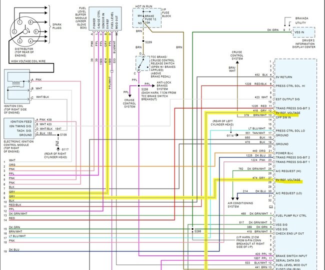
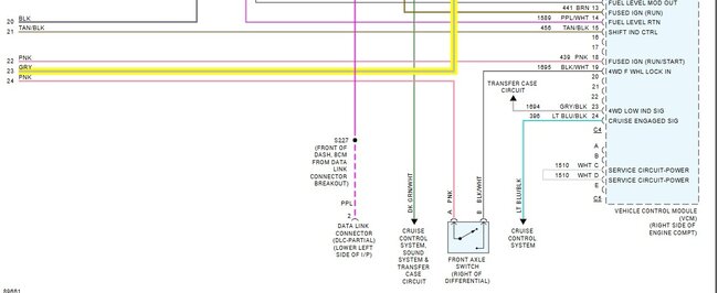
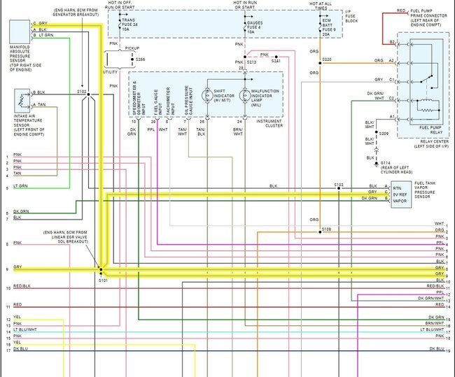
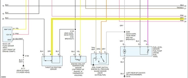
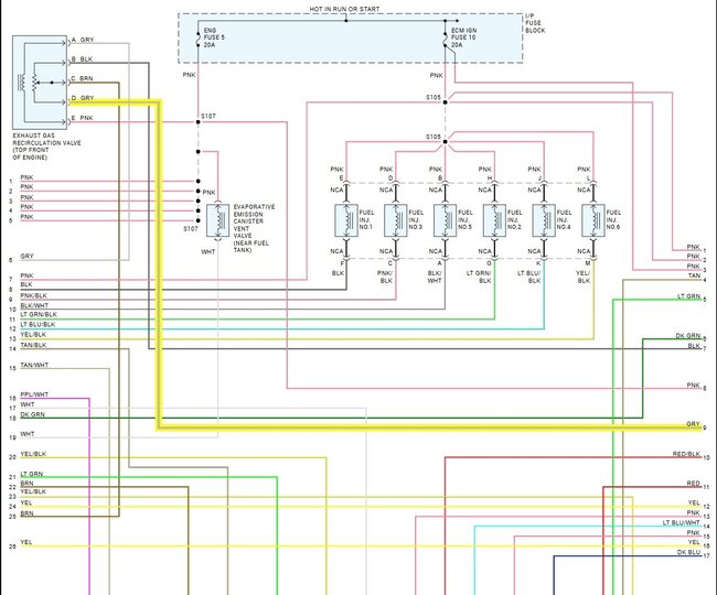
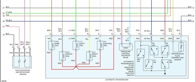
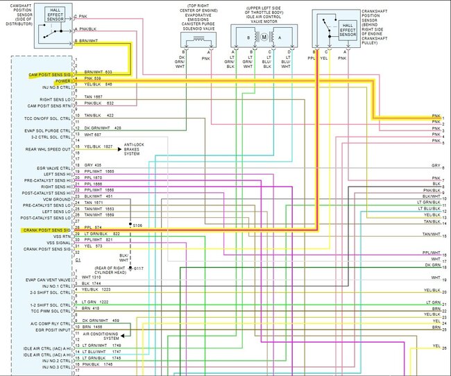
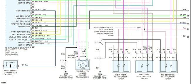
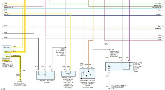
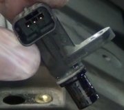
These are the PCM/ECM wiring diagrams, starting with the 5v reference side of the computer. Diagrams 1 & 2 are top and bottom, and so on. The 5 volt Ref on this vehicle is a Grey wire, you'll noticed its shared with a bunch of sensors, and even though there are 2 wires coming from the computer labelled "5v. Ref Voltage", this reference voltage is most like definitely shared internally inside the computer, so if it's a shorted sensor when hot, causing this fault, it can pull every 5v Ref down, this can even shut the computer down.
The MAP sensor or Throttle Position Sensor (TPS) will be the two easiest sensors to get to being right on top of the engine to check when the vehicle stalls out, since the fault sounds to be repeatable pretty easy, I would back probe the connector at the MAP sensor with a back probing pin, so you're ready to check it when the engine stalls out. You can put the other lead of a meter just to Battery negative for now. Key On, the grey wire should read a solid 5volts.
Diagrams 6,7 (top and bottom) are the last page of the engine computer diagrams, they don't have any reference voltage wires on them with the grey wire, but do have the Cam and Crank sensors, which are a 12volt feed to them, being Hall effect sensors.
I do see a Mass Air Flow sensor as well (MAF), that's another live data point to look at on a scan tool during the fault, I would expect the computer to store some sort of trouble code as well, if it's not, it may be losing power, and left long enough would end up erasing any diagnostic trouble codes.
Let us know what you find, or if you need any other service information.
https://www.2carpros.com/articles/how-to-use-a-voltmeter
https://www.2carpros.com/articles/engine-stalls
Images (Click to make bigger)
Thursday, January 9th, 2025 AT 12:10 PM
