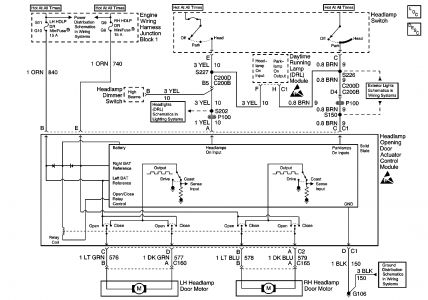
That is a strange problem frank. I was looking through the schmatics and it looks like the actuator control module pretty much does it all....I have included a pic of the diagram and the description and operation....
When the headlamp switch is turned to the HEAD position, battery voltage is applied to the headlamp opening door actuator control module through circuit 10. Battery voltage is constantly applied to the headlamp opening door actuator control module from the LH HDLP DR MiniFuse 15A and from the RH HDLP DR, MiniFuse 15A. The headlamp opening door actuator control module is grounded by G106. The LH headlamp door opens when battery voltage is applied to the LH headlamp opening door motor through circuit 840, the headlamp opening door actuator control module, and circuit 576. Ground is applied through circuit 577. The RH headlamp door opens when battery voltage is applied to the RH headlamp door motor through circuit 740, the headlamp opening door actuator control module, and circuit 578. Ground is applied to circuit 579. When the headlamp switch is moved to the OFF position, battery voltage is no longer applied to the headlamp opening door actuator control module through circuit 10. The LH headlamp door closes when battery voltage is applied to the LH headlamp door motor through circuit 577 and ground is applied to circuit 576. The RH headlamp door closes when battery voltage is applied to the RH headlamp door through circuit 579 and ground is applied to circuit 578.
I hope this helps ya out alittle...I would get a test light and go at it and find out where the voltage is coming from that is keeping that motor runing...
Cly
SPONSORED LINKS
Wednesday, August 8th, 2007 AT 7:26 PM