Disconnect the negative battery cable.
Remove the turn signal switch
Unclip the horn and key light ground wires.
Remove the four screws that hold the bearing housing to the lock housing.
Remove the snapring from the upper end of the steering shaft.
Remove the bearing housing from the shaft.
Remove the lock plate spring and lock plate from the steering shaft.
Remove the ignition key, then remove the screw and lift out the buzzer/chime switch.
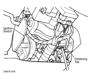
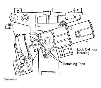
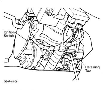
Remove the two screws attaching the ignition switch to the column jacket.
Remove the ignition switch by rotating the switch 90 degrees on the rod then sliding off the rod.
Remove the two mounting screws from the dimmer switch and disengage the switch from the actuator rod.
Remove the two screws that mount the bell crank and slide the bell crank up in the lock housing until it can be disconnect from the ignition switch actuator rod.
To remove the lock cylinder and lock levers place the cylinder in the lock position and remove the key.
Insert a small diameter screwdriver or similar tool into the lock cylinder release holes and push into the release spring loaded lock retainers. At the same time pull the lock cylinder out of the housing bore.
Grasp the lock lever and spring assembly and pull straight out of the housing.
If necessary the lock housing may be removed from the column jacket by removing the hex head retaining screws.
To install:
Installation is the reverse of removal. If the lock housing was removed tighten the lock housing screws to 90 inch lbs. (10 Nm).
To install the dimmer switch, firmly seat the push rod into the switch. Compress the switch until two 1 / 8 in. (3mm) drill shanks can be inserted into the alignment holes. Reposition the upper end of the push rod in the pocket of the wash/wipe switch. With a light rearward pressure on the switch, install the two screws.
Grease and assemble the two lock levers, lock lever spring and pin.
Install the lock lever assembly in the lock housing. Seat the pin firmly into the bottom of the slots and make sure the lock lever spring leg is firmly in place in the lock casting notch.
Install the ignition switch actuator rod from the bottom through the oblong hole in the lock housing and attach it to the bell crank onto its mounting surface. The gearshift lever should be in the park position.
Place the ignition switch on the ignition switch actuator rod and rotate it 90 degrees to lock the rod into position.
To install the ignition lock, turn the key to the lock position and remove the key. Insert the cylinder far enough into the housing to contact the switch actuator. Insert the key and press inward and rotate the cylinder.
Monday, June 8th, 2020 AT 1:35 PM
(Merged)


