Hello
There is a self test you can perform. I have attached that. Make sure you check the fuses it talks about first.
For a Diagnostic check you need the DRB scan tool.
DIAGNOSTIC PROCEDURE
In order to diagnose the instrument cluster function, a DRB scan tool and the proper Body Diagnostic Procedures are required. See: Body and Frame Body Control Systems Body Control Module Testing and Inspection Procedures
As a quick diagnosis, the cluster will perform a function check immediately after the ignition is switched to the RUN/START position. The electronic display, odometer and transmission range indicator and all warning lamps except:
"Â Cruise
"Â Fog lamps
"Â High beam
"Â Low fuel
"Â Turn signal will illuminate for a brief period.
If the cluster is not receiving CCD bus messages, the cluster will appear nonfunctional except for the continuously illuminated airbag indicator and NO BUS message displayed.
If the cluster is not receiving CCD bus messages, refer to the Powertrain Management/Computers and Control Systems/pre-diagnostic test described in proper Body Diagnostic Procedures or refer to the Instrument Panel, Gauges and Warning Indicators/Instrument Panel/Instrument Cluster Self-Diagnostic Test.
INSTRUMENT CLUSTER SELF-DIAGNOSTICS
Initiate instrument cluster self-diagnostic by depressing the odometer/trip reset button while turning the ignition key to the OFF/RUN/START position. This will cycle an electronic display segment check and illumination in sequence of all CCD bus activated cluster warning indicators. There are four Check (CHECK) functions:
1. CHECK 1, checks the gauges.
2. CHECK 2, checks the warning lamps.
3. CHECK 3, checks the odometer/trip meter.
4. CHECK 4, Transmission Range Indicator for the automatic transmission or the autostick transmission. If the diagnostic procedure determines that a replacement of an instrument cluster component is required, refer to the proper component removal procedure.
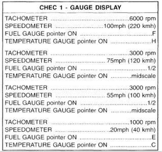
CHECK I
If all gauges fail to move, replace Cluster Printed Circuit (PC) Board.
If any gauge fails to move, replace the gauge assembly
If any gauge(s) is not in the proper position, replace Cluster Printed Circuit Board.
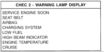
CHECK 2
If any lamp does not light, check lamp.
If lamp is not OK, replace lamp.
If lamp is OK, replace Cluster Printed Circuit Board.
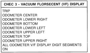
CHECK 3
If any V/F segment does not light, replace Odometer/Transmission Range Indication.
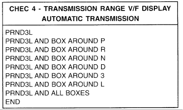
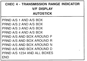
CHECK 4
If any V/F segment does not light, replace Odometer/Transmission Range Indication.
Hope this helps
SPONSORED LINKS
Tuesday, October 21st, 2008 AT 10:07 PM


