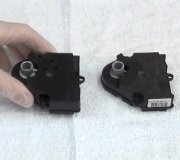
Blend door actuator location and replacement?

Tiny
WOLF762
  • MEMBER
  • 2016 FORD FUSION
  • 2.5L
  • 4 CYL
  • 2WD
  • AUTOMATIC
  • 100,000 MILES
While using my A/C the driver's side vents blow cold air but the passenger side vents blow warm air. I suspect the passenger side blend door actuator is the culprit. I'm unable to find good information on the location of this component for the 2013 and newer model year Fusions. Is it accessible from behind the glove compartment or do I need to remove trim panels on the driver's side, center console, or passenger side?
Thursday, August 8th, 2019 AT 4:40 AM

25 Replies

Tiny
SCGRANTURISMO
  • MECHANIC
  • 4,897 POSTS
Hello,

I have included the information that you have requested in the diagrams down below. I have included the factory removal and installation guides for your vehicle for the passenger side temperature control door actuator. Please go through this guide and get back to us with how everything turns out.

Thanks,
Alex
2CarPros
Was this
answer
helpful?
Yes
No
Friday, October 2nd, 2020 AT 9:58 AM
Tiny
DR359679
  • MEMBER
  • 3 POSTS
  • 2016 FORD FUSION
  • 2WD
  • AUTOMATIC
  • 39,000 MILES
Heat on driver side cod on passenger side. How to replace the driver side blend door?
Was this
answer
helpful?
Yes
No
Wednesday, October 14th, 2020 AT 12:49 PM (Merged)
Tiny
KASEKENNY
  • MECHANIC
  • 18,907 POSTS
Hi,

Here is the procedure. Let me know if you need more information. Thanks
Was this
answer
helpful?
Yes
No
+3
Wednesday, October 14th, 2020 AT 12:49 PM (Merged)
Tiny
DR359679
  • MEMBER
  • 3 POSTS
I'm not seeing any blend door on the driver's side. I replaced the blend door on the passenger side. I'm still getting cold air on the passenger side and hot air on the driver's side. Please help
Was this
answer
helpful?
Yes
No
Wednesday, October 14th, 2020 AT 12:49 PM (Merged)
Tiny
KASEKENNY
  • MECHANIC
  • 18,907 POSTS
Do you have dual temp zones? Meaning can you set the drive side to a different temperature then the passenger side?
Was this
answer
helpful?
Yes
No
-2
Wednesday, October 14th, 2020 AT 12:49 PM (Merged)
Tiny
DR359679
  • MEMBER
  • 3 POSTS
No it's not dual climate control.
Was this
answer
helpful?
Yes
No
Wednesday, October 14th, 2020 AT 12:49 PM (Merged)
Tiny
KASEKENNY
  • MECHANIC
  • 18,907 POSTS
Okay. Then you should have a a lever on the passenger side actuator that controls both doors. More than likely this has come off or arm/door is frozen.

I would remove this and inspect the passenger side actuator and see if one of the arms is not connected.
Was this
answer
helpful?
Yes
No
-1
Wednesday, October 14th, 2020 AT 12:49 PM (Merged)
Tiny
ISTAL
  • MEMBER
  • 1 POST
  • 2016 FORD FUSION
  • 2.0L
  • 4 CYL
  • 2WD
  • AUTOMATIC
  • 57,000 MILES
My car listed above has cold air blowing out the passenger side but hot air blowing out the driver side. Is this a blend door malfunction?
Was this
answer
helpful?
Yes
No
Wednesday, October 14th, 2020 AT 12:49 PM (Merged)
Tiny
KASEKENNY
  • MECHANIC
  • 18,907 POSTS
Yes. I suspect this is the case. You have two actuators. One for each side. I attached the process for replacing this. Let us know what happens.

Thanks

https://www.2carpros.com/articles/replace-blend-door-motor
Was this
answer
helpful?
Yes
No
+1
Wednesday, October 14th, 2020 AT 12:50 PM (Merged)
Tiny
JENOS83
  • MEMBER
  • 2 POSTS
  • 2015 FORD FUSION
  • 1.5L
  • 4 CYL
  • 2WD
  • AUTOMATIC
  • 80,000 MILES
I have air only coming through the head/face vents even when I have the floor and/or defog vents selected. Hot and cold selection still works fine. From what I've read this sounds like the blend door actuator, but I'm unsure of the location on my model.
Was this
answer
helpful?
Yes
No
Wednesday, October 14th, 2020 AT 12:50 PM (Merged)
Tiny
KASEKENNY
  • MECHANIC
  • 18,907 POSTS
This is actually called the distribution actuator. The blend door actuator is what mixes the air to give you the temp that you are requesting.

I attached the process. Unfortunately they say you need to remove the steering column. I attached that process as well.

Let me know if you have questions. Thanks
Was this
answer
helpful?
Yes
No
+4
Wednesday, October 14th, 2020 AT 12:50 PM (Merged)
Tiny
BMDOUBLE
  • MECHANIC
  • 1,139 POSTS
The air distribution blend door motor is on the driver side of the plenum and the steering column must be removed. Here are the removal and Installation instructions for the steering column:

Steering Column
Removal
NOTE: Removal steps in this procedure may contain installation details.
Remove the steering column shrouds.
Refer to: Steering Column Shrouds (501-05 Interior Trim and Ornamentation).
Remove the steering wheel.
Refer to: Steering Wheel (211-04 Steering Column, Removal and Installation).
Release the clips and position aside the instrument panel finish panel.

Remove the bolts and the instrument panel finish panel.

Disconnect the electrical connector.

Remove the retainers and disconnect the steering column electrical connectors.

Remove and discard the bolt.
Torque : 18 lb. Ft (25 Nm)
Position aside the upper shaft from the lower shaft.

NOTE: The deployable steering column electrical connector retaining tabs are not easily accessible. Using an inspection mirror and needle-nose pliers may help in viewing and releasing the electrical connector retaining tabs.
Depress the locking tabs and disconnect the collapsible steering column module electrical connector.

Remove and discard the bolts and remove the column.
Torque : 18 lb. Ft (25 Nm)

Installation
NOTE: Transfer parts as needed.
To install, reverse the removal procedure.
Was this
answer
helpful?
Yes
No
+1
Wednesday, October 14th, 2020 AT 12:50 PM (Merged)
Tiny
JENOS83
  • MEMBER
  • 2 POSTS
Thanks for the info! If my steering column wasn't involved I'd probably attempt it, but I might as well take it to the dealer and get the recalls taken care of.
Was this
answer
helpful?
Yes
No
Wednesday, October 14th, 2020 AT 12:50 PM (Merged)
Tiny
BMDOUBLE
  • MECHANIC
  • 1,139 POSTS
You're welcome!
Was this
answer
helpful?
Yes
No
Wednesday, October 14th, 2020 AT 12:50 PM (Merged)
Tiny
SCOTT371
  • MEMBER
  • 1 POST
  • 2014 FORD FUSION
  • 1.5L
  • 4 CYL
  • 2WD
  • AUTOMATIC
  • 72,000 MILES
My car is only blowing air from the vents, when I switch it to floor or defroster nothing happens. I replaced the blend door actuator on the driver side. Where is the one that controls the mode in where it goes is located. Very frustrating. Any help would be great. HVAC air mode actuator?
Was this
answer
helpful?
Yes
No
Wednesday, October 14th, 2020 AT 12:50 PM (Merged)
Tiny
KASEKENNY
  • MECHANIC
  • 18,907 POSTS
This is called the distribution door actuator. I attached the procedure. Let me know if you have questions. Check out the diagrams (Below). Please let us know if you need anything else to get the problem fixed. Thanks
Was this
answer
helpful?
Yes
No
-1
Wednesday, October 14th, 2020 AT 12:50 PM (Merged)
Tiny
DEMUSR
  • MEMBER
  • 1 POST
  • 2012 FORD FUSION
  • 2.2L
  • 4 CYL
  • 2WD
  • AUTOMATIC
  • 80,000 MILES
My car is a Hybrid. Bad blend door actuator on passenger side needs replaced. I have the glove box out and have located it but I can only see one screw on the actuator and one on the mount. What else needs to be removed to replace this? Update: Found the three 5.5mm bolt heads. Cannot fit my 1/4" socket with ratchet on two of the three.
Was this
answer
helpful?
Yes
No
-1
Wednesday, October 14th, 2020 AT 12:50 PM (Merged)
Tiny
JACOBANDNICKOLAS
  • MECHANIC
  • 109,885 POSTS
Hi and thanks for using 2CarPros.com.

Here is a link that describes replacement in general:

https://www.2carpros.com/articles/replace-blend-door-motor

Here are the directions specific to your vehicle from Alldata. The attached pictures correlate with these directions. These directions also include the recalibration process.
__________________

Temperature Blend Door Actuator - RH, Dual-Zone EATC
Removal and Installation

1. Remove the passenger air bag module.

2. Disconnect the RH temperature blend door actuator electrical connector.

3. Remove the 2 RH temperature blend door actuator bracket screws.

4. Detach the wire harness from the RH temperature blend door actuator bracket.

5. Remove the RH temperature blend door actuator.

6. To install, reverse the removal procedure.

7. NOTE: The purpose of the module actuator position calibration is to allow the HVAC module to reinitialize and calibrate the actuator stop points. To carry out calibration, carry out the following steps.

Remove the Smart Junction Box (SJB) fuse 15 for at least one minute.

8. NOTE: When the ignition switch is switched to the ON position, the HVAC module will initialize and calibrate the actuators. Calibration of the actuators will take approximately 30 seconds.

Reinstall SJB (Smart Junction Box) fuse 15. Turn the ignition switch to the ON position and wait 30 seconds before verifying correct DEFROST/PANEL/FLOOR operation.
___________________________________

Let me know if this helps.

Take care,
Joe
Was this
answer
helpful?
Yes
No
+2
Wednesday, October 14th, 2020 AT 12:50 PM (Merged)
Tiny
MAC1956
  • MEMBER
  • 2 POSTS
  • 2011 FORD FUSION
  • 3.0L
  • 6 CYL
  • 2WD
  • AUTOMATIC
  • 130,000 MILES
The buttons light up, but when pressed, the vents do not change. Which actuator and where is it located? Thank you
Was this
answer
helpful?
Yes
No
Wednesday, October 14th, 2020 AT 12:50 PM (Merged)
Tiny
ASEMASTER6371
  • MECHANIC
  • 52,797 POSTS
Good evening.

It is in the dash. The instrument cluster has to be removed to access. It is on the side of the heater case. I believe you can see it but not remove it without the dash removed.

It is number 7 in the picture This is a very involved procedure. Are you planning on doing this job yourself?

Roy

Removal and Installation

1. Remove the instrument panel. For additional information, refer to Instrument Panel and Console See: Dashboard / Instrument Panel > Removal and Replacement > Instrument Panel.

2. Disconnect the LH temperature blend door actuator electrical connector.

3. Remove the 2 LH temperature blend door actuator screws.

4. Remove the LH temperature blend door actuator.

5. Disconnect the in-vehicle temperature sensor aspirator hose connection.

6. Disconnect the DEFROST/PANEL/FLOOR mode door actuator electrical connector.

7. Remove the 3 DEFROST/PANEL/FLOOR mode door actuator and cam assembly screws.

8. Remove the DEFROST/PANEL/FLOOR mode door actuator and cam assembly.

9. To install, reverse the removal procedure.

10. NOTE: The purpose of the module actuator position calibration is to allow the HVAC module to reinitialize and calibrate the actuator stop points. To carry out calibration, carry out the following steps.

Remove the Smart Junction Box (SJB) fuse 15 for at least one minute.

11. NOTE: When the ignition switch is switched to the ON position, the HVAC module will initialize and calibrate the actuators. Calibration of the actuators will take approximately 30 seconds.

Reinstall SJB fuse 15. Turn the ignition switch to the ON position and wait 30 seconds before verifying correct DEFROST/PANEL/FLOOR operation.

The procedure for removing the dash.

Nstrument Panel

Removal and Installation

1. Remove the steering wheel. For additional information, refer to Steering Column See: Steering Wheel > Removal and Replacement > Steering Wheel.

2. Remove the floor console. For additional information, refer to Console - Floor, Fusion, Milan See: Console > Removal and Replacement > Console - Floor or Console - Floor, MKZ See: Console > Removal and Replacement > Console - Floor.

3. Remove the selector lever or the gearshift lever. For additional information, refer to See: Shifter A/T > Removal and Replacement.

4. Remove the LH and RH instrument panel side finish panels.
- Pull the sides of the instrument panel side finish panels away from the instrument panel to release the retaining tabs.

5. Remove the LH and RH weatherstrips from the front door openings near the instrument panel.

6. Remove the LH and RH A-pillar trim panels. For additional information, refer to Interior Trim and Ornamentation See: Trim Panel > Removal and Replacement.

7. Remove the LH and RH lower cowl panels. For additional information, refer to Interior Trim - Exploded View in Interior Trim and Ornamentation See: Trim Panel > Removal and Replacement > Interior Trim - Exploded View.

8. If equipped, remove the RH lower instrument panel insulator.

9. Disconnect the 2 electrical connectors located at the LH lower cowl.

ImageOpen In New TabZoom/Print

10. Disconnect the small gray and the black electrical connectors from the Smart Junction Box (SJB).

ImageOpen In New TabZoom/Print

11. Remove the 2 screws and position the hood release handle aside.

ImageOpen In New TabZoom/Print

12. Disconnect the bulkhead electrical connector and the antenna cable located at the RH lower cowl. If equipped, disconnect the satellite antenna.

ImageOpen In New TabZoom/Print

13. Fully lower the glove compartment door and disconnect the 2 A/C electrical connectors.

ImageOpen In New TabZoom/Print

14. Disconnect the electrical connector and the 2 wire harness retainers located on the floor between the front seats.

ImageOpen In New TabZoom/Print

15. Remove the 2 nuts and position the steering column pinch bolt cover aside.

ImageOpen In New TabZoom/Print

16. Remove and discard the steering column shaft bolt.
- To install, use a new steering column shaft bolt and tighten to 20 Nm (177 lb-in).

ImageOpen In New TabZoom/Print

17. NOTE: Index-mark the steering column shaft position to the steering gear for reference during installation.

Detach the upper steering column shaft from the steering column.

18. Disconnect the in-vehicle temperature sensor aspirator hose from the heater core and evaporator core housing, if equipped, in the following sequence.

1. Separate the aspirator hose retaining clips away from the heater core and evaporator core housing.

2. Pull the aspirator hose away from the heater core and evaporator core housing.

ImageOpen In New TabZoom/Print

19. Remove the Instrument Cluster (IC). For additional information, refer to Instrumentation, Message Center, and Warning Chimes See: Instrument Cluster / Carrier > Removal and Replacement > Instrument Panel Cluster (IPC).

20. Through the IC opening, remove the 2 IC opening bolts.
- To install, tighten to 23 Nm (17 lb-ft).

21. Remove the 3 instrument panel center support bolts.
- To install, tighten to 20 Nm (177 lb-in).

22. Remove the LH and RH instrument panel lower bolts from the outer sides of the instrument panel.
- To install, tighten to 8 Nm (71 lb-in).

23. NOTICE: To avoid damaging the instrument panel, the aid of an assistant is required to carry out this step.

NOTICE: Make sure that all electrical connectors and wiring are not hindered before removing the instrument panel or damage to the components may occur.

Remove the instrument panel.

- Through the instrument panel side finish panel openings, remove the 3 instrument panel side bolts.

- To install, tighten to 23 Nm (17 lb-ft).

24. NOTICE: To avoid damaging the instrument panel, the aid of an assistant is required when positioning the instrument panel to the vehicle.

NOTICE: Make sure that all electrical connectors and wiring are correctly routed when installing the instrument panel or damage to the components may occur.

To install, reverse the removal procedure.
Was this
answer
helpful?
Yes
No
Wednesday, October 14th, 2020 AT 12:50 PM (Merged)

Please login or register to post a reply.

Sponsored links