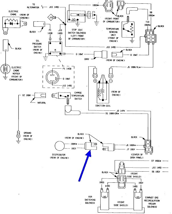
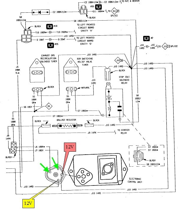
There were at least three versions of ignition systems used that year with the 318 c.I. These diagrams are of the most basic system with just one pick-up coil inside the distributor. If that is what you have, most of the testing can be done right at the five-pin plug for the ignition module. For the best accuracy for this type of problem, a test light works better, but you can use a digital voltmeter if that's all you have. The test light should be the old style with an inexpensive incandescent light bulb inside.
Remove the plug, then, with the ignition switch in the "run" position, check for 12 volts on the terminals with the red and yellow call-outs pointing to them. Next, use an ohm meter to check the continuity between the two terminals with the green arrows. Expect to find between about 500 to 1000 ohms. If you find an open circuit, that points to a defective pick-up coil. To double-check that, unplug the connector with the blue arrow, then check the continuity at that point.
The last connection is the ground for the module. That is made through the mounting bolts. Be sure those are tight and not rusty.
If those tests are okay, for electrical issues that leaves the ignition coil and the module. If the switching transistor on the module is shorted, you'll get one spark from the ignition coil when the ignition switch is turned off, as I mentioned previously. That single spark proves the ignition coil is okay. If you don't see that spark, with the ignition switch still in "run", go back to the five-pin plug and use a jumper wire to briefly ground the terminal with the yellow call-out. If the coil is good, you'll see a single spark from it when you remove that jumper wire. That nice strong spark proves the coil and the wiring are okay and 12 volts is feeding the coil.
The only thing left is the ballast resistor. That is bypassed during cranking, so if it is defective, the engine would start and run as long as you hold the ignition switch in the "crank" position.
The last things are mechanical problems. First, be sure the distributor shaft is turning. If it is not, suspect the nylon teeth are worn off the camshaft sprocket. Next, the air gap for the pick-up coil is critical. It needs to be.012" and that has to be measured with a brass feeler gauge. A standard steel gauge will stick magnetically to the assembly and give a false feel.
I had a problem once with one of my cars where I couldn't get the rotor off to replace it. I cracked it off with a hammer and screwdriver, and when it split, part of it pushed on the pick-up coil resulting in a crank / no-start. I found the air gap had been increased to.022". That was enough to stop it from generating its signal pulses. By the way, hammering on the rotor is a bad idea. The upper half of the distributor shaft that sits above the mechanical advance fly-weights is real easy to bend. If that is bad enough, some of the teeth on the reluctor, or star wheel, will hit the pick-up coil, resulting in more damage, or some teeth will rotate away too far, then no signal pulses will be generated for a few cylinders. If the rotor is hopelessly stuck, a better choice is to use an air-powered cutoff tool to cut it apart.
Images (Click to make bigger)
Wednesday, April 8th, 2020 AT 2:19 PM


