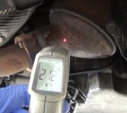
If it stalls like this, you have a good chance of the intake manifold gasket is leaking vacuum. That will cause the engine to stall.
Roy
REMOVAL
1. Open hood and install protective covers.
2. Ensure ignition key is in OFF position.
3. Drain coolant from radiator.
4. Disconnect negative battery lead and secure it out of the way.
5. Remove fuel cap to relieve fuel tank pressure.
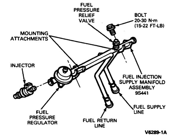
Fuel Pressure Relief Valve/Test Port
imageOpen In New TabZoom/Print
6. Release pressure from fuel system at the fuel pressure relief valve using EFI Pressure Gauge T8OL-9974-B or equivalent. The fuel pressure relief valve is located on the fuel injection supply manifold assembly in the upper RH corner of the engine compartment. To gain access to the fuel pressure relief valve, the valve cap must first be removed.
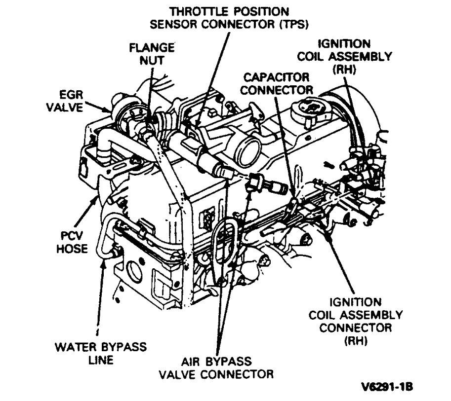
Connector/Component Locations
imageOpen In New TabZoom/Print
7. Disconnect electrical connectors at:
a. Throttle position sensor.
B. Air bypass valve.
C. Injector wiring harness at main engine harness and at water temperature indicator sensor.
D. Air charge temperature sensor.
E. Engine coolant temperature sensor.
F. Ignition control assembly.
8. Disconnect upper intake manifold vacuum fitting connections by disconnecting:
a. Vacuum lines at upper intake manifold vacuum tree. Labeling the hose locations with tape is recommended to aid reinstallation.
B. Vacuum line to EGR valve.
C. Vacuum line to fuel pressure regulator.
D. Canister purge line.
9. Remove throttle linkage shield, and disconnect throttle linkage, cruise control. Unbolt accelerator cable from bracket and position cable out of the way.
10. Disconnect air intake hose and crankcase vent hose.
11. Disconnect PCV system by disconnecting hose from fitting on underside of upper intake manifold.
12. Loosen hose clamp on water bypass line at lower intake manifold, and disconnect hose.
13. Disconnect EGR tube from EGR valve by removing flange nut.
14. Remove five upper intake manifold retaining bolts.
15. Remove upper intake manifold and air throttle body assembly.
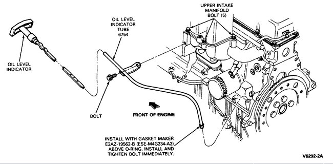
Oil Dipstick And Bracket
imageOpen In New TabZoom/Print
16. Remove engine oil dipstick bracket retaining bolt.
Springlock Coupling Remover
imageOpen In New TabZoom/Print
17. Remove springlock coupling retainer clips from fuel inlet and return fittings.
WARNING: Relieve fuel system pressure before disconnecting coupling.
18. Disconnect the push connect fitting at the fuel supply manifold and fuel return lines.
19. Disconnect the electrical connectors from all four fuel injectors and move harness aside.
20. Remove two fuel supply manifold retaining bolts. Carefully remove fuel supply manifold and injectors.
NOTE: Injectors can be removed from the fuel supply manifold at this time by exerting a slight twisting/pulling motion.
21. Remove four bottom retaining bolts from lower manifold.
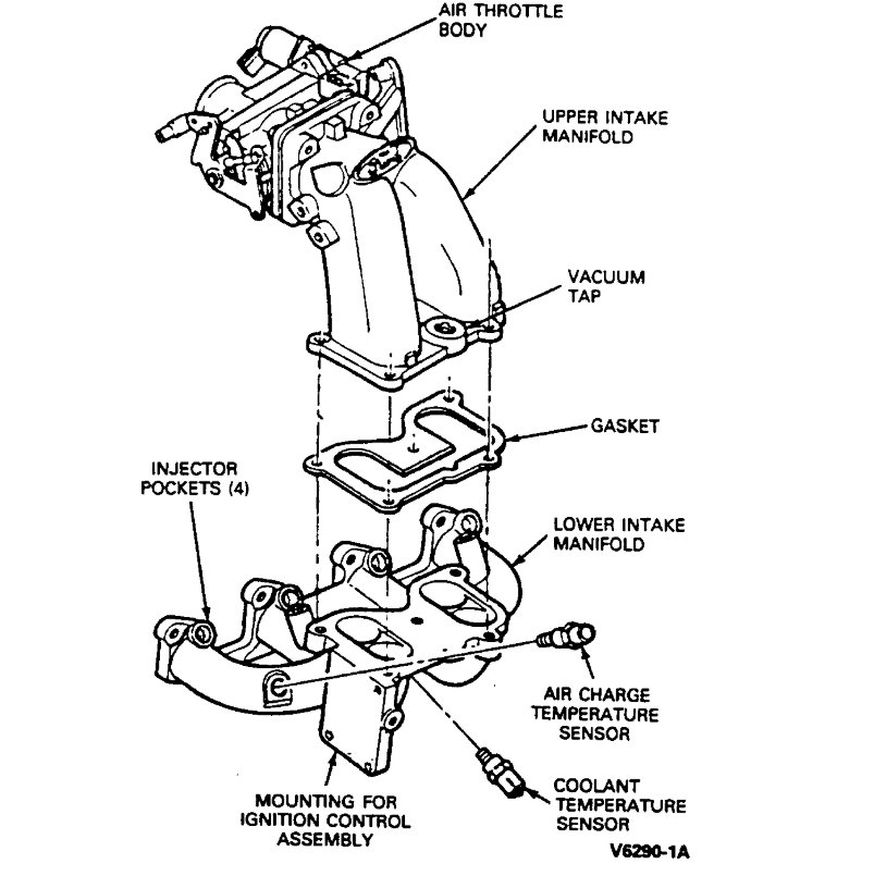
Intake Manifold Assembly
imageOpen In New TabZoom/Print
22. Remove four upper retaining bolts from lower manifold.
NOTE: The front two bolts also secure an engine lift bracket. Remove lower intake manifold assembly.
INSTALLATION
1. Clean and inspect the mounting faces of the fuel charging manifold assembly and the cylinder head. Both surfaces must be clean and flat.
2. Clean and oil manifold bolt threads.
3. Install a new gasket.
4. Position the lower manifold assembly to head and install engine lift bracket. Install four upper manifold retaining bolts fingertight.
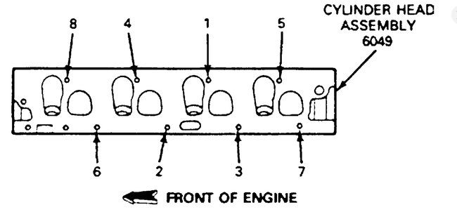
Fig. 5 Lower Intake Manifold Bolt Tightening Sequence
imageOpen In New TabZoom/Print
5. Install four remaining manifold bolts. Tighten all bolts to 20-30 Nm (15-22 ft lb) following the tightening sequence.
6. Install the fuel supply manifold and injectors with two retaining bolts. Tighten bolts to 20-30 Nm (15-22 ft lb).
7. Connect four electrical connectors to injectors.
8. Ensure that gasket surfaces of upper and lower intake manifolds are clean.
9. Place a new service gasket on the lower intake manifold assembly and place the upper intake manifold in position.
Fig. 4 Upper Intake Manifold Tightening Sequence
imageOpen In New TabZoom/Print
10. Install five retaining bolts and tighten in sequence to 20-30 Nm (15-22 ft lb).
NOTE: The three bolts with stud heads go in hole positions 2, 3 and 4.
11. Install engine oil dipstick and retaining bolt.
12. Connect fuel supply and fuel return lines to fuel supply manifold.
13. Reinstall spring-lock coupling retaining clips on fuel inlet and return fittings.
14. Connect EGR tube to the EGR valve. Tighten to 25-30 Nm (18-28 ft lb).
15. Connect the water bypass line. Tighten clamp to 1.4-2.2 Nm (12-20 in lb).
16. Connect the PCV system hose to the fitting on the underside of the upper intake manifold.
17. Connect upper intake manifold vacuum connections:
a. Vacuum lines at upper intake manifold vacuum tree.
B. EGR valve.
C. Fuel pressure regulator.
D. Canister purge line.
18. Hold accelerator cable bracket in position on upper manifold and install retaining bolts. Tighten bolt to 13.5-20.5 Nm (10-15 ft lb).
19. Install accelerator cable to bracket.
20. Connect accelerator cable and cruise control. Install throttle linkage shield.
21. Connect electrical connectors to:
a. Throttle position sensor.
B. Injector wiring harness.
C. Injector wiring harness at water temperature indicator sensor.
D. Air charge temperature sensor.
E. Engine coolant temperature sensor.
F. Ignition Control assembly.
G. Air bypass valve.
22. Connect air intake hose and crankcase vent hose.
23. Connect negative battery cable.
24. Install engine coolant.
25. Replace fuel pressure relief cap, then build up fuel pressure as follows: without starting the engine, turn key back and forth at least six times from ON to OFF position, leaving key on for 15 seconds each time; then check for fuel leaks.
26. Use EEC self-test connector to check proper EEC-IV system functioning.
27. Start engine and allow to run at idle until engine temperature stabilizes. Check for cooling system leaks.
28. Check engine idle.
29. Remove protective covers and close hood.
Images (Click to make bigger)
SPONSORED LINKS
Saturday, July 18th, 2020 AT 12:29 PM
(Merged)
