Is engine 3.3 or 3.5 L?
Our database shows only 3.3 L.
This is an inteference engine and miracluously quite a number of engines have survived without any damages to the valves so keep your fingers crossed.
When turning the crankshaft, ensure it does not meet any resistance and DO NOT force. Back off if any resistance is felt. Keep pistons away from TDC before turning the camshafts to desired position.
After camshafts have been aligned then only align crankshaft.
Installation (Frontier, Pathfinder, QX4 & Xterra)
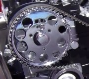
1. Install timing belt when engine is cold. Ensure No. 1 cylinder is at TDC on compression stroke. Crankshaft sprocket mark should align with mark on rear cover. See Fig. 5. If removed, install timing belt tensioner and tensioner spring.
NOTE: If stud for tensioner spring is removed, apply thread sealant to stud threads before installing.
2. Turn tensioner clockwise fully outward with hexagon wrench, and temporarily tighten lock nut. Align White lines on timing belt with punch marks on camshaft sprockets and crankshaft sprocket. See Fig. 6. Point arrow on timing belt toward front belt cover. There should be 40 teeth between left and right camshaft sprockets, and 43 teeth between left camshaft sprocket and crankshaft sprocket.
3. If engine was overhauled or reassembled (rocker covers removed), go to step 6. If only the timing belt was replaced, go to next step.
4. Loosen tensioner lock nut. Using hex wrench, turn tensioner clockwise and counterclockwise at least 2 times. Tighten tensioner lock nut. Turn crankshaft clockwise at least 2 revolutions, then slowly set No. 1 cylinder at TDC on compression stroke. Apply 22 lbs. (10 kg) of force to belt (downward direction) midway between camshaft sprockets. Belt deflection should be 0.51-0.59" (13-15 mm). If not, readjust belt tension.
5. Install lower and upper belt covers. Install crankshaft pulley. Tighten bolt to specification. To complete installation, reverse removal procedures. Fill and bleed cooling system. Adjust drive belts
to proper tension.
6. Loosen rocker shaft bolts to relieve belt tension caused by camshafts. Loosen tensioner lock nut. Using Allen wrench, rotate tensioner by turning Allen wrench clockwise 70-80 degrees. Temporarily tighten lock nut. Rotate crankshaft clockwise at least 2 revolutions.
7. Slowly return cylinder No. 1 to TDC of compression stroke. Using Push/Pull Gauge (J-38387), apply 22 lbs. (10 kg) of pressure to timing belt between right camshaft sprocket and tensioner. Hold tensioner in position with Allen wrench, and loosen tensioner lock nut.
8. Place a.0206" (.5 mm) feeler gauge under tensioner pulley between pulley and timing belt, and rotate crankshaft clockwise until feeler gauge is centered between tensioner pulley and timing belt (timing belt will move about 2.5 teeth). See Fig. 7. Tighten tensioner lock nut to specification.
9. Rotate crankshaft to remove feeler gauge. Rotate crankshaft clockwise at least 2 revolutions, then slowly set cylinder No. 1 at TDC of compression stroke. While applying 22 lbs. (10 kg) of pressure, measure timing belt deflection halfway between camshaft sprockets. If
deflection is not.51-.59" (13-15 mm), repeat steps 6-8. To complete installation, reverse removal procedure. Fill and bleed cooling system. Adjust drive belts to proper tension.
Images (Click to make bigger)
Tuesday, June 2nd, 2020 AT 12:58 PM
(Merged)


