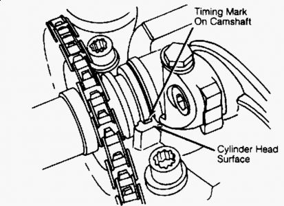
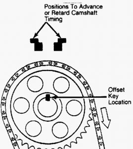
Removal & Installation 1. A master link (split) timing chain is available for replacement without dismantling engine. Remove air cleaner, valve cover, and spark plugs. Use a chain link remover to remove master link from timing chain. 2. Remove old link and insert new master link with new chain attached. Turn crankshaft (by hand) slowly in direction of rotation while feeding new chain in and removing old chain. Ensure that chain does not slip on sprockets. Install master link from rear so retainer will be at front of engine. 3. Install connecting link clip with closed end facing direction of rotation. Rotate crankshaft through one complete revolution and check that camshaft timing mark is aligned. See Fig. 4 . To complete installation, reverse removal procedure. Fig. 2: Timing Chain Installation (SOHC) Courtesy of MERCEDES-BENZ OF NORTH AMERICA. Fig. 3: Timing Chain Installation (DOHC) Courtesy of MERCEDES-BENZ OF NORTH AMERICA. CAMSHAFTS Removal 1. Remove air cleaner and valve cover. Set No. 1 piston at TDC. Mark on flange of camshaft must be in alignment with edge on cylinder head. See Fig. 4 . 2. Mark camshaft sprocket and timing chain in relation to each other. Carefully remove chain tensioner nut (under spring tension), sealing ring and tensioner spring. 3. Remove camshaft bolt and sprocket. Remove rocker arm bearing caps. Remove and mark ball sockets from spring retainers. Remove camshaft. Remove Woodruff key and spacing ring from camshaft. Check lobes of camshaft for wear or scoring. Replace camshaft if necessary. Installation To install, reverse removal procedure. Make sure ball sockets are installed in original positions. Ensure that identifying marks on camshaft sprocket and timing chain are aligned. Check alignment of mark on camshaft with edge of cylinder head. See Fig. 4 . NOTE: DO NOT rotate engine using camshaft sprocket bolt. DO NOT rotate engine in reverse direction. Prior to rotating crankshaft, switch ignition off and pull out plug for TDC transmitter of ignition distributor (Green cable) on switching unit. NOTE: On models equipped with level control system the pressure pump is driven from front of camshaft. With pump removed, remove socket head cap screw from front of camshaft and remove drive coupling. Fig. 4: Camshaft Timing Marks CAMSHAFT TIMING Checking & Adjusting 1. With ignition off, disconnect TDC transmitter plug or switching unit plug. Never rotate engine in reverse direction while checking camshaft timing. 2. Remove air cleaner and valve cover. Rotate engine using crankshaft bolt. DO NOT use camshaft sprocket bolt to rotate engine. Turn engine until camshaft lobe of No. 1 intake valve is pointing downward (intake valve closed). 3. Replace No. 1 intake rocker arm with an Adjustable Rocker Arm (102 055 00 01), Adjustment Screw (102 050 02 20 164), and Nut (000936 008009 163). Adjust clearance to zero. 4. Install dial indicator with indicator stem resting vertically on valve spring retainer. Set indicator preload at .12" (3.0 mm) and zero dial indicator. Turn crankshaft in normal direction of rotation until valve is open .08" (2.0 mm). 5. Crankshaft pointer should be at 12 degrees after TDC. If necessary, use an offset key to adjust camshaft timing to specification. Reverse removal procedure to complete installation. See Fig. 5 .


Crank woodruff key at 12:00
SPONSORED LINKS
Tuesday, September 8th, 2009 AT 9:46 AM


