Here are the installation procedures from our database.
Installation
1. Install camshaft gear, if removed. Apply oil onto camshaft journals, lobes and gears. Install camshafts so reference mark on intake camshaft gear and exhaust camshaft gear align. See Fig. 20. Using a screwdriver, adjust gear position so HLA's are not lifted by cam lobes.
Fig. 20: Installing Camshafts
2. Coat hydraulic lash adjuster, camshaft journals and camshaft journals cylinder head surfaces with engine oil. Install HLA into original location (if removed).
CAUTION:Install thrust caps first to prevent damage to camshaft.
CAUTION:DO NOT allow sealant to contact camshaft. Ensure camshaft remains horizontal when installing thrust caps or thrust clearance surface will be damaged.
NOTE: Thrust caps on right cylinder head are identified by numbers, with "5" at timing belt end of engine. Thrust caps on left cylinder head are identified by letters, with "B" at timing belt end of engine.
Fig. 21: Camshaft Thrust Cap Bolt Tightening Sequence
Fig. 22: Identifying Camshaft Bearing Sealant Application Areas
3. Install thrust caps onto cylinder head. Hand tighten cap bolts in sequence, using several steps, until caps are fully seated on cylinder head. See Fig. 21. Apply sealant at designated areas on cylinder head. See Fig. 22.
NOTE: Camshaft bearing caps on right cylinder head are identified by numbers, with No. 1 at timing belt end of engine. Camshaft bearing caps on left cylinder head are identified by letters, with "A" at timing belt end of engine.
4. Install remaining camshaft bearing caps (with bolts) loosely. Tighten camshaft bearing cap bolts in sequence to specification using several steps. See Fig. 41. DO NOT allow camshafts to bind.
5. Lubricate NEW camshaft oil seal and push in by hand. Using hammer and suitable diameter pipe, tap camshaft oil seal into cylinder head. Apply sealant onto NEW blind cap. Using soft-face hammer, tap blind cap into cylinder head.
6. Install coolant outlet. Tighten retaining bolts to specification. Install seal plate. Tighten retaining bolts to specification.
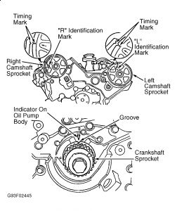
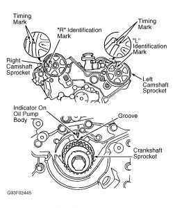
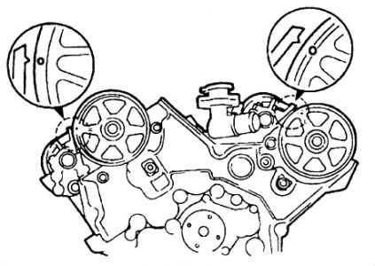
7. Hold camshaft from turning by using a wrench on camshaft hex. Install left and right camshaft pulleys as identified by "L" and "R" stamped on them. Ensure camshafts pulleys are installed so identification marks can be seen, and timing marks align with camshaft knock pins. Tighten camshaft pulley bolts to specification.
8. Before installing valve cover and gasket, apply sealant onto specified areas on cylinder head. See Fig. 9. Apply sealant onto valve cover, and install NEW gasket into valve cover. Install valve cover and gasket.
9. Install and tighten valve cover bolts in sequence to specification using several steps. See Fig. 43. To install remaining components, reverse removal procedure. Tighten all fasteners to specification. Fill and bleed cooling system.
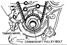
10. Rotate crankshaft so No. 1 cylinder is at TDC on compression stroke. Ensure timing mark on crankshaft pulley aligns with TDC mark on timing belt cover. Coat distributor "O" ring and drive blade on distributor with engine oil. Align groove on distributor body drive blade. Install distributor and hold-down bolt.
Images (Click to make bigger)
Wednesday, July 31st, 2019 AT 5:14 PM
(Merged)


