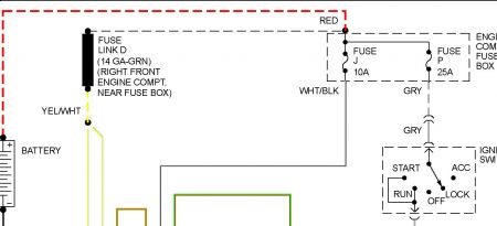
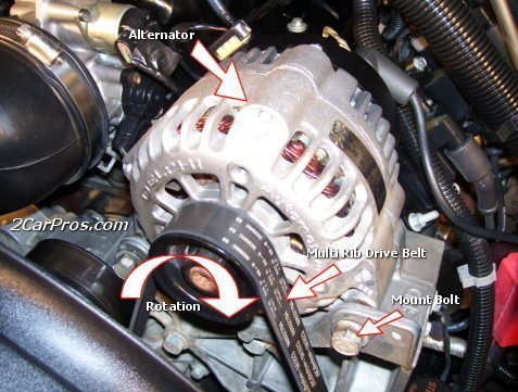
Well, I found a book but the diagrams are really confusing. Can you tell me if your generator has an external fan on the front that you can push on with your thumb? Next, I think you have the 65 amp generator with the regulator bolted to the back. There's a three-wire plug on the regulator, with yellow / white, white / black, and light green / red wires.
If you have only a total of three wires, (black / orange, white / black, and orange / light blue), you have the 100 amp generator with an external voltage regulator. Since you have the more common dual black / orange wires, I'm using the 65 amp diagram.
Start by checking for voltage on the two black / orange wires. They should both have full battery voltage all the time. By the way. Those wires are never supposed to be unplugged because that will degrade the solid mechanical connection, and that will lead to overheating of the terminals and rapid failure. Replacement units come with a new plug already installed, and you are supposed to splice and solder the wires to the vehicle's harness. Weird, huh?
Next, the yellow / white wire in the regulator plug must also have battery voltage all the time. If it is missing, there is a fusible link attached to the starter relay. The wire has nothing in common with the starter circuit. It is just used as a convenient tie point. Of the six wires shown on that terminal, the fuse link is a gray 16 gauge wire. That is the weak link in the chain. The wire is smaller diameter than the main yellow / white wire so that's where it will burn open. The insulation is designed to not melt or burn. Test it by tugging on it. If it acts like a wire, it's ok. If it acts like a rubber band, it's burned open. You can buy replacement fuse link wire from the auto parts stores according to color. You can usually use less than half of the piece they give you so you'll have enough for another repair later.
Next, measure the voltage on the green / red wire. There should be 0 volts with the ignition switch off, less than about 1.5 volts with the switch on, (that terminal is grounding the dash light), and it should pop up to near battery voltage when the system is working. Battery voltage on both sides of the dash light turns it off.
Also, when the system is charging, there will be around 5 - 7 volts on the white / black wire. That voltage is tapped off the output and is what tells the voltage regulator to raise the voltage on the green / red wire to turn off the warning light.
Let me know what you find on those wires.
Caradiodoc
Monday, June 1st, 2020 AT 2:17 PM
(Merged)


