Hello - thompson001
Sorry for the delay. . .. . ...minor technical difficulties.
First by your response of owning the car for some time and knowing how to work the controls; I feel I may have offended you. So I apologize for that.
Please understand that we deal with literally thousands of questions/people. These people such as you; have hundreds of different circumstances, many different levels of understanding of not only their vehicle but of mechanics etc. So as we review things we don't have all of that information. I was just dealing with someone that got the car from their father. Last week, that person had been driving the car for 6 months and the item never came up until then. Also, there are thousands of different types of cars, trucks, models, etc that we deal with. Though we may have worked on many, we may not have worked on your specific. So, when we, or in this case, when I asked certain questions, it is in no way to offend. . ..it is so you and I are on the same page so that you can be better assisted as quick as possible.
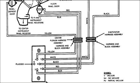
I still believe you have a couple of problems. . .. . .. . .some with the recir door etc. I have attached the information that I think will help you. I don't think you are getting proper vacuum to certain doors and they are opening as they should.
I reviewed all the TSBs for your model and there are not any that deal with this.
Now if you cannot read the diagrams, even if you right/click copy paste etc to your computer, please make sure you tell me so I can try to make them bigger.
Well, I did a quick preview and it is hard to read so I am not sure how it will do if you right/click copy. So. . .. . .what I did was blow it up and past in parts. . ...you may have to copy print and tape together. I did it in order of the pics. . ...So for the first pic. . ...there are 3 different parts. ETC
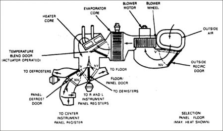
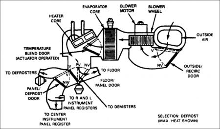
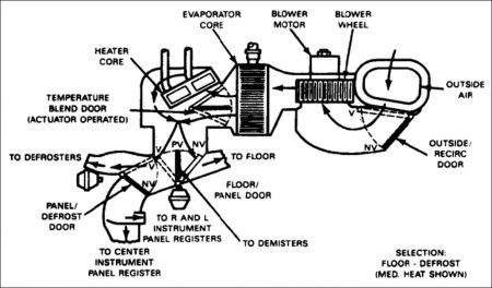
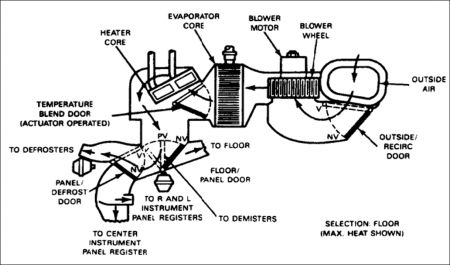
As you see the chart. . ...when you select a position it tells you what to look for on the vacuum.
Let me know if this helps or not. . .. . .. . .. . ...and we will see if we can do more.
Non-Trouble Code Procedures
Notes
Testing For Vacuum At The Control Assembly
To test the EATC vacuum system, start the engine and depress the function buttons slowly from one position to another. A momentary hiss should be heard as each button is depressed from one position to another, indicating that vacuum is available at the control assembly. A continuous hiss at the control assembly indicates a major leak somewhere in the system. It does not necessarily indicate that the leak is at the control assembly.
Checking Vacuum Supply Lines
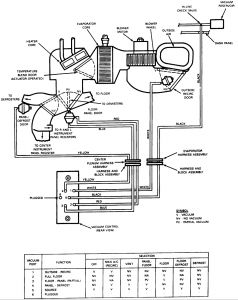
If a momentary hiss cannot be heard as each function button is depressed from one position to another, check for a kinked, pinched, or disconnected vacuum supply hose (illustration). Also, inspect the check valve between the vacuum intake manifold and the vacuum reservoir to ensure it is working properly.
Testing Vacuum Motors
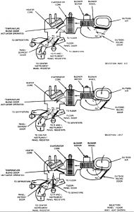
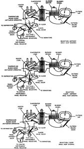
If a momentary hiss can be heard as each function button is depressed from one position to another, vacuum is available at the control assembly. Cycle the function buttons through each position with the blower on HIGH and check the location(s) of the discharge air. The airflow schematic and vacuum control chart shows the vacuum motors applied for each function selection along with an airflow diagram of the system (see illustrations). The airflow diagram shows the position of each door when vacuum is applied, along with the no-vacuum positions. With this chart, airflow for each position of the control assembly can be determined. If a vacuum motor fails to operate, the motor can readily be found because the airflow will be incorrect.
If a vacuum motor is inoperative, check the operation of the motor with a Rotunda Vacuum Tester 021-00014 or equivalent. If the vacuum motor operates properly, the vacuum hose is probably pinched, kinked, disconnected or has a leak.
Locating A Leak When Functioning Normally At Idle
If the function system functions normally at idle, but goes to defrost during acceleration, a small leak exists in the system. The leak can be located by shutting off the engine and using a gauge to check for vacuum loss while selectively blocking off vacuum hoses.
To check electrical system operation between the control assembly head connector and the blend door actuator, refer to Self Diagnostics Test.
The First Pic
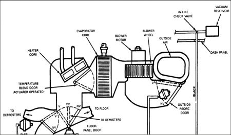
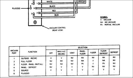
The Second Pic
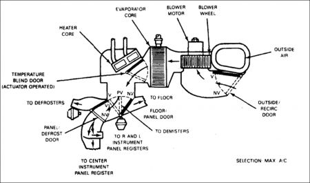
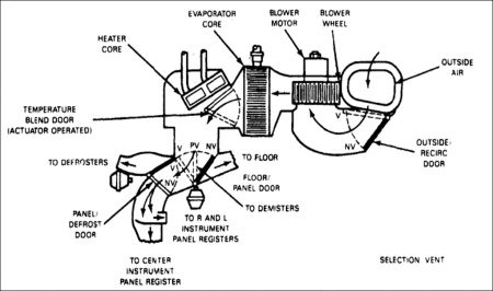
The Third Pic
Saturday, December 20th, 2008 AT 1:47 PM
