Did you replace the H02s, when you replaced the Catalytic convertor ? Also what type of new cats were fitted OEM/Aftermarket/universal ?
DTCS P0130-P0133, PO136-P0139, P0150-P0153, P0156-P159, P0171-P0172, P0174-P0175, P1137-P1139, P1157-P1159, P1171-P1172 & P1185-P1196: HO2S CIRCUIT MALFUNCTION
There are 4 Heated Oxygen Sensors (HO2S) located in the exhaust system. Primary HO2S-1 "A" is located before left side catalytic converter and secondary HO2S-2 "A" is located after left side catalytic converter. Primary HO2S-1 "B" is located before right side catalytic converter and secondary HO2S-2 "B" is located after right side catalytic converter. Secondary HO2S-2 measure oxygen content after catalytic converters to monitor operating efficiency of converters.
Each HO2S is electrically heated to ensure sensor achieves operating temperature as quickly as possible after start-up. ECM energizes HO2S heater using a Pulse Width Modulation (PWM) signal which starts low and increases within 30 seconds to desired heater temperature. Primary HO2S heaters are wired in parallel and secondary HO2S heaters are wired in parallel for synchronous ECM control of each heater pair.
If front HO2S wiring is crossed, vehicle will operate properly until sensors reach operating temperature. ECM will then cause one bank of cylinders to run very rich and the other bank to run very lean. This will cause engine to misfire, idle rough and emit black smoke, with possible catalytic converter damage.
Diagnostic Aids
Indications of HO2S failure may be a strong smell of rotten eggs until default condition is initiated, high CO readings and/or MIL is illuminated. Check for contaminated sensor, poor connections, loose terminals, and open or shorted wires. Ensure wiring to primary sensors is not crossed.
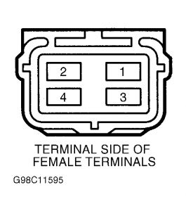
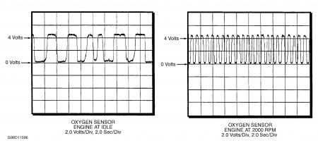
With engine running at normal operating temperature, measure HO2S output voltage between HO2S 4-pin connector terminals No. 1 and 2. See Fig. 7 . Output voltage on primary HO2S should change between approximately 0.2 volts (rich mixture) and approximately 4.7 volts (lean mixture). Using a Snap-On Personal Automotive Computer (PAC), compare wave pattern with known-good wave patterns. See Fig. 8 . Oxygen content of exhaust gases after catalytic converter should be nearly constant, causing little voltage change in secondary HO2S.
Measure HO2S heater resistance between sensor connector terminals No. 3 and 4. See appropriate WIRING DIAGRAMS article. See Fig. 7 . HO2S heater resistance at 68 °F (20 °C) should be approximately 5.7 ohms.
Fig. 7: Identifying 4-Pin Sensor Connector Terminals

Fig. 8: Identifying Known-Good HO2S Wave Patterns

Monday, April 19th, 2010 AT 3:51 AM


