Did you retrieve the code using the MIL ? (flashing).. i'm not showing a code 12 on my DTC list ?? also is it an aftermarket immobolizer you have fitted ? let me know
1.If indicator lights operate, but all gauges are inoperative, go to next step. If all gauges and indicator lights are inoperative, go to step 5).
2.Remove and inspect fuse No. 16 (15-amp) in Power Distribution Center (PDC). PDC is located in engine compartment, near battery. If fuse is okay, go to next step. If fuse is blown, locate and repair cause of blown fuse. Install new fuse and recheck system operation.
3.Measure voltage between ground and power side of fuse No. 16 fuse holder. If battery voltage is present, go to next step. If battery voltage is not present, locate and repair open circuit.
4.Remove instrument cluster. See REMOVAL & INSTALLATION . Reconnect negative battery cable. Measure voltage between ground and terminal No. 9 (Pink wire) at instrument cluster 10-pin Black connector. If battery voltage is present, reinstall instrument cluster and go to ACTUATOR TEST . If battery voltage is not present, repair open circuit between fuse No. 16 in PDC and instrument cluster 10-pin Black connector.
5.Remove and inspect fuse No. 9 (10-amp) in junction block. Junction block is located behind right side kick panel. If fuse is okay, go to next step. If fuse is blown, locate and repair cause of blown fuse. Install new fuse and recheck system operation.
6.Turn ignition on. Measure voltage between ground and power side of fuse No. 9 fuse holder. If battery voltage is present, go to next step. If battery voltage is not present, locate and repair open circuit between ignition switch and junction block.
7.Turn ignition on. Set parking brake and observe instrument cluster brake warning light. If brake warning light is on, go to next step. If brake warning light is off, go to step 9).
8.Turn parking lights on and adjust instrument panel lights dimmer rheostat to full bright position. If instrument panel lights are on, go to ACTUATOR TEST . If instrument panel lights are off, go to step 10).
9.Remove instrument cluster. See REMOVAL & INSTALLATION . Reconnect negative batter cable. Turn ignition on. Measure voltage between ground and terminal No. 8 (White/Black wire) at instrument cluster 10-pin Black connector. If battery voltage is present, go to ACTUATOR TEST . If battery voltage is not present, locate and repair open circuit.
10.Remove instrument cluster. See REMOVAL & INSTALLATION . Using an ohmmeter, check for continuity between ground and terminal No. 1 (Black/Light Green wire) at instrument cluster 10-pin Black connector. If continuity exists, go to ACTUATOR TEST . If continuity does not exist, locate and repair open in ground circuit.
ACTUATOR TEST
Diagnostic Aids
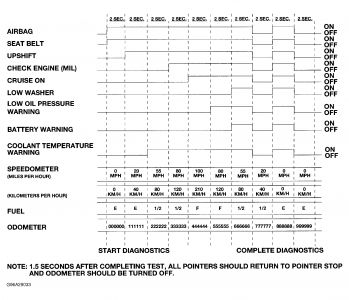
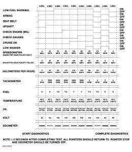
Instrument actuator test will put instrument cluster into self-diagnostic mode. In this mode, instrument cluster will position each of the gauge needles at various specified calibration points, and turn all Chrysler Collision Detection (CCD) data bus message-controlled indicator lights on and off at specified time intervals. See Fig. 1 or Fig. 2 . Successful completion of actuator test will confirm that instrument cluster circuitry, gauges and indicator lights are capable of operating properly. If test is successful, a problem may still exist with CCD data bus, Powertrain Control Module (PCM) or Air Bag Control Module (ACM).
If an individual gauge does not respond properly or at all during actuator test, remove instrument cluster. Check tightness of suspect gauge mounting screws on printed circuit board. If screws are loose, reinstall instrument cluster and retest. If screws are tight, replace instrument cluster.
If an individual indicator light does not illuminate during actuator test, remove instrument cluster. Check indicator light bulb and bulb holder. Repair as necessary and retest. If indicator bulb is okay and bulb holder is installed properly, replace instrument cluster.
Actuator Test
Turn ignition off. Depress and hold down trip odometer reset button. Turn ignition on. DO NOT start engine. Release trip odometer reset button. Compare operation of suspect gauge(s) and/or indicator light(s) with chart. See Fig. 1 or Fig. 2 .
Instrument cluster will exit self-diagnostics mode at completion of test, or if ignition switch is turned off. If instrument cluster gauge(s) and/or indictor light(s) do not respond properly during actuator test, see DIAGNOSTIC AIDS before replacing instrument cluster. Repeat actuator test if necessary.
Fig. 1:

Fig. 2:

AIR BAG INDICATOR LIGHT TEST
If AIR BAG warning light illuminates for 12 seconds or more, or stays on all the time, a system malfunction exists and trouble code will be stored. For air bag system testing procedures, see the AIR BAG RESTRAINT SYSTEM article.
If air bag indicator light does not illuminate when ignition is on, replace air bag indicator bulb and retest. If air bag indicator light still does not illuminate, perform PRELIMINARY DIAGNOSIS .
If after performing PRELIMINARY DIAGNOSIS and ACTUATOR TEST , air bag indicator light and instrument cluster circuitry is okay, diagnosis of air bag system and Chrysler Collision Detection (CCD) data bus should be performed.
For air bag system testing procedures, see the AIR BAG RESTRAINT SYSTEM article. For CCD data bus testing, check for opens and shorts in CCD data bus circuits.
Monday, January 19th, 2009 AT 6:27 AM


