DTC P1122: PEDAL POSITION SENSOR CIRCUIT 1 LOW VOLTAGE
NOTE:After each repair, clear DTCs. See CLEARING DIAGNOSTIC TROUBLE CODES/ECM RESET PROCEDURE under SELF-DIAGNOSTIC SYSTEM. Turn ignition off and then on. Read DTCs to verify repair is complete. For DLC and ECM connector terminal identification, see CONNECTOR IDENTIFICATION. For wiring diagrams and all other terminal identification, see WIRING DIAGRAMS. If wire color codes are different, use connector pin numbers for wire identification.
DTC Description
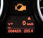
Pedal Position Sensor (PPS) circuit 1 low voltage. This DTC is an OBD-II fault. Check Engine Indicator is activated after 2 consecutive trips with fault present. Red MIL (above message center) and Amber MIL (above message center) is illuminated after one trip with fault present. A message is displayed on message center.
Monitoring Conditions
Ignition on for more than 5 seconds.
System Default Action
When Red MIL is activated (DTC logged; first trip), ECM:
Switches off throttle motor (via relay).
Initiates throttle "limp home" mode (engine speed controlled to between 1000-1250 RPM by fuel cutoff to cylinders).
Inhibits idle speed control.
Inhibits cruise control.
Inhibits traction control/stability control.
Possible Causes
PPS to ECM sensing circuit 1 (sensor pin No. 4) wire open or high resistance.
PPS power supply fault.
PPS failure.
Diagnostic Test Procedure
Disconnect negative battery cable. Disconnect ECM connector EM81. Disconnect the PPS connector. Measure resistance between ECM harness connector EM81 terminal No. 9 and PPS harness connector terminal No. 4. Is resistance greater than 5 ohms? If yes, repair high resistance between ECM harness connector EM81 terminal No. 9 and PPS harness connector terminal No. 4. If no, go to next step.
Reconnect negative battery cable. Turn ignition on. Measure voltage between PPS terminal No. 4 and ground. Is voltage greater than 5 volts? If yes, repair short to voltage. If no, go to next step.
Turn ignition off. Measure resistance between PPS terminal No. 4 and ground. Is resistance less than 10,000 ohms? If yes, repair short to ground. If no, go to next step.
Reconnect ECM connector EM81. Turn ignition on. Measure voltage between PPS terminal No. 1 and ground. Is voltage less than 4 volts? If yes, go to next step. If no, go to step 6.
Turn ignition off. Disconnect ECM connector EM83. Measure resistance between ECM harness connector EM83 terminal No. 5 and PPS harness connector terminal No. 1. Is resistance greater than 5 ohms? If yes, repair high resistance between ECM harness connector EM83 terminal No. 5 and PPS harness connector terminal No. 1. If no, check ECM power supplies. See DTC P0560: VEHICLE VOLTAGE MALFUNCTION.
Measure resistance between PPS terminal No. 3 and ground. Is resistance greater than 5 ohms? If yes, go to next step. If no, install a new APP sensor.
Disconnect ECM connector EM83. Measure resistance between ECM harness connector EM83 terminal No. 13 and PPS harness connector terminal No. 3. Is resistance greater than 5 ohms? If yes, repair high resistance between ECM harness connector EM83 terminal No. 13 and PPS harness connector terminal No. 3. If no, check ECM grounds. If ECM grounds are okay, possible ECM failure.
Friday, November 27th, 2009 AT 6:52 AM


