Most OBDII readers are OBDI compliant just check before buying
RETRIEVING CODES (NON-SCAN)
Before entering on-board diagnostics, refer to SERVICE PRECAUTIONS. Turn ignition switch to OFF position. Locate Data Link Connector (DLC), next to fuse block. Connect voltmeter positive lead to Data Link Connector (DLC) MFI diagnosis terminal and negative lead to ground terminal. See Fig. 1 .
Turn ignition switch to ON position. Voltmeter (analog) will display trouble codes by 12-volt pulses of voltmeter needle. Trouble codes are retrieved in numerical order. A constant repetition of short 12-volt pulses indicates system is normal. If system is abnormal, voltmeter will pulse between zero and 12 volts.
Codes will appear on voltmeter as long and short 12-volt pulses. Long pulses represent tens; short pulses represent ones. For example: 4 long pulses and 3 short pulses indicate Code 43. After recording fault code(s), perform necessary repair(s) to indicated circuit(s). See FAULT CODES.
Fig. 1: Identifying Self-Diagnostic Connector Location
Courtesy of HYUNDAI MOTOR CO.
RETRIEVING CODES (SCAN TESTER)
NOTE:If scan tester is needed to perform diagnostic test with key in START position, an auxiliary power source is needed to operate scan tester. Use optional Battery Harness (09391-33500 ).
NOTE:For specific operating procedures using scan tester, see instruction manual.
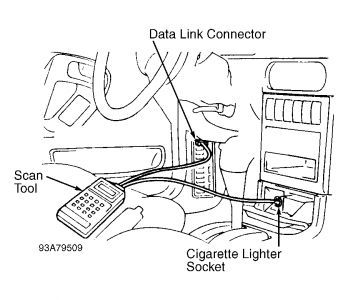
Before entering on-board diagnostics, refer to SERVICE PRECAUTIONS. Turn ignition switch to OFF position. Locate Data Link Connector (DLC), next to fuse block. Connect power source terminal of scan tester to cigarette lighter socket. See Fig. 2 .
Connect scan tester to Data Link Connector (DLC). Turn ignition on. Read and record scan tester self-diagnostic output. Perform necessary repair(s). See FAULT CODES.

SPONSORED LINKS
Friday, November 21st, 2008 AT 8:49 AM


