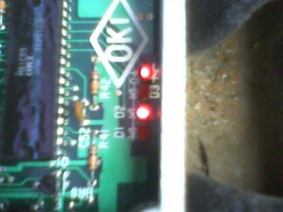
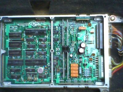
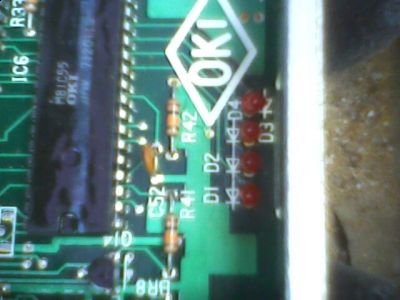
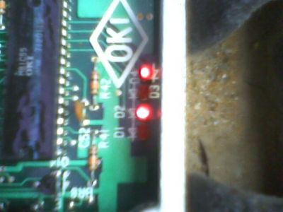
The D1 to D4 are the circuit board schematic diodes.
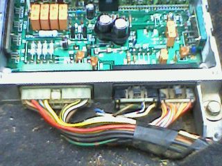
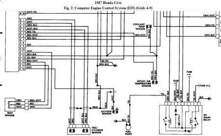
I have the testing diagnostic for the various circuits but it is not the correct position as the ECU connectors unless you have the Diagnostic Harness Checker. Refer to lower diagram for wire colors. You can back probe the connectors by removing the ECU from its mounting points.
A = biggest connector ( white) you need to backprobe the C connector.
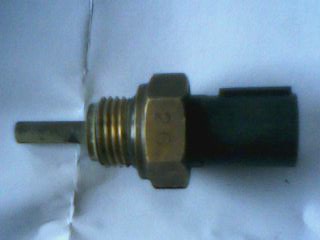
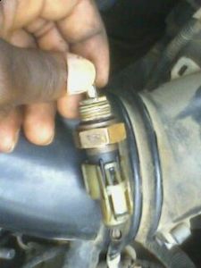
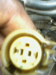
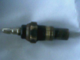
Note the wire colors at ECT, you have the correct pix of it.
SELF-DIAGNOSTIC LIGHTS NO. 1 & 4 ON OR LIGHT BLINKS 5 TIMES
NOTE: Check control box vacuum hose routing before proceeding with trouble shooting.
1. Ensure MAP sensor vacuum hoses are properly connected. Disconnect vacuum hose from MAP sensor and plug open end of hose. Disconnect vacuum hose No. 21 from throttle body (vacuum hose between MAP sensor and throttle body on CRX Si). Connect vacuum pump to hose and apply vacuum.
2. If vacuum does not hold, replace hose. If vacuum remains constant, plug system checker harness between control unit and connector. Connect positive voltmeter probe to terminal C15 (Red/White wire) and negative probe to terminal C14 (Blue/White wire). Turn ignition on and check voltage.
3. Voltage should be 4.75-5.25 volts. If voltage is not within specification, replace ECU and retest. If voltage is within specification, connect voltmeter positive probe to terminal C11 (White/Blue wire) and negative probe to terminal C14 (Blue/White wire).
4. Voltage should be 2.76-2.96 volts. If voltage is not within specification, check and repair open/short circuit in Blue/White or White/Blue wires (White/Red or Brown/White wires on CRX Si) between MAP sensor and ECU. Check for faulty MAP sensor.
5. If voltage is within specification, connect vacuum pump to MAP sensor. Ensure voltage varies as vacuum is applied. If voltage does not vary, replace MAP sensor. If voltage varies, replace ECU and retest.
SELF-DIAGNOSTIC LIGHTS NO. 2 & 8 ON OR LIGHT BLINKS 10 TIMES
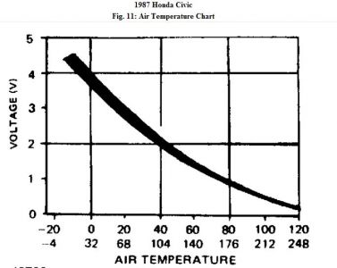
1. Plug system checker harness between ECU and connector. Connect voltmeter positive probe to terminal C5 (White/Red wire) and negative probe to terminal C12 (Green/White wire). Turn ignition on. Ensure voltage reading is correct for intake air temperature.
2. If voltage is correct, replace ECU and retest. If voltage is not correct, turn ignition off. Check for open/short circuit in White/Red and Green/White wires (Red/Yellow and Brown/Black wires on CRX Si) between intake air temperature sensor and ECU. Repair wiring if necessary. If wiring checks okay, check intake air temperature sensor. Replace sensor if defective. If sensor tests okay, replace ECU and retest.
Sunday, March 15th, 2009 AT 12:41 AM
