Here are the trouble shooting procedures.
DTC P0715: (FLASH CODE 15) MAINSHAFT SPEED SENSOR
NOTE: DTC P0715 (FLASH CODE 15) doesn't always mean an electrical problem in mainshaft speed sensor or circuit; this DTC can also be caused by a mechanical problem in transaxle.
1 . Ensure mainshaft and countershaft speed sensors are installed properly. Disconnect mainshaft speed sensor connector and measure resistance between sensor connector terminals.
2 . If resistance is not 400 -600 ohms, replace mainshaft speed sensor. If resistance is 400 -600 ohms, disconnect PCM 25 -pin connector "B". Check continuity between ground and PCM 25 -pin connector "B" terminals No. 15 (Orange/Blue wire) and No. 14 (White/Blue wire).
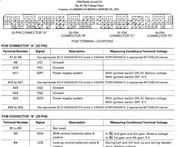
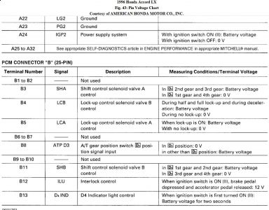
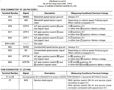
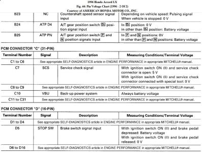
3 . If continuity exists, repair short to ground in Orange/Blue and White/Blue wires between PCM and mainshaft speed sensor. If continuity does not exist, reconnect mainshaft speed sensor connector. Measure resistance between PCM 25 -pin connector "B" terminals No. 15 (Orange/Blue wire) and No. 14 (White/Blue wire).
4 . If resistance is not 400 -600 ohms, go to next step. If resistance is 400 - 600 ohms, perform DTC P0720 (FLASH CODE 9) diagnostic, check for loose PCM connectors and replace PCM with known good part, as necessary.
5 . Disconnect mainshaft speed sensor connector. Check continuity of Red wire between PCM 25 -pin connector "B" terminal No. 15 (Orange/Blue wire) and mainshaft speed sensor connector. If continuity exists, go to next step. If continuity does not exist, repair open Orange/Blue wire between PCM 25 -pin connector and mainshaft speed sensor connector.
6 . Check continuity of White wire between PCM 25 -pin connector "B" terminal No. 14 (White/Blue wire) and mainshaft speed sensor connector. If continuity exists, check for loose PCM connectors and replace PCM with known good part, as necessary. If continuity does not exist, repair open White/Blue wire between PCM 25 -pin connector and mainshaft
speed sensor connector.
Tuesday, October 27th, 2009 AT 11:05 AM


