REMOVAL & INSTALLATION
See Figures 1, 2, 3 and 4
Disconnect the negative battery cable. If so equipped, disable the Supplemental Restraint System (SRS), as described in Chassis Electrical .
Remove the wheel cover or hubcap from the front wheel and then remove the center cap.
Pull out the 4mm cotter pin and loosen but do not remove the spindle nut. Loosen the lugnuts.
Raise and safely support the front of the vehicle on jackstands. Double check the stand placement and the security of the support.
Remove the wheel lug nuts and the wheel.
Pry up the lock tabs and remove the large spindle nut.
Drain the transaxle.
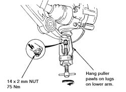
Using a ball joint separator, remove the lower arm ball joints from the knuckle. Disconnect the tie rods from the steering knuckle.
Fig. 1: Use a ball joint separator to disconnect the ball joints

On cars using a lower control arm, disconnect the stabilizer bar retaining bolts and free the bar.
On later cars with the "wishbone" suspension, remove the damper fork bolt and the damper pinch bolt.
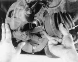
To remove the halfshaft, hold the knuckle and move it outwards while sliding the shaft out of the hub.
Fig. 2: Hold the knuckle and move it outwards while sliding the shaft out of the hub

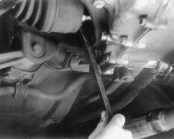
At the inboard or transaxle end, pry the CV-joint out about 1/2 in. (13mm). Prying the axle outward causes an internal snapring to come out of its locking groove. Pry carefully to avoid damaging the oil seal.
Fig. 3: Pry the joint out of the differential case ...

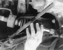
Carefully pull the inboard side of the driveshaft out of the differential case.
Fig. 4: ... then carefully pull the inboard side of the driveshaft out of the differential case

SPONSORED LINKS
Saturday, January 12th, 2008 AT 12:06 PM


