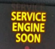
Hi,
Anything is possible. It could be the sensor, wiring, connector, TCM, and so on. Here is my concern: The vehicle came with a 5 year 60,000 mile power-train warranty, so if it is the transmission, it should be covered by the manufacturer's warranty. If you do something wrong, they may void the warranty. What I would recommend is to contact a dealer with your VIN number and confirm it is still under warranty. I don't actually know the in service date, but you are good as far as mileage.
The only way I can confirm would be to have you complete diagnostics. I will provide the directions. I noted you indicated no knowledge, so you may not feel comfortable doing this or have the tooling. Regardless, I want you to have them.
_______________________________________
2016 Nissan-Datsun Altima Sedan L4-2.5L (QR25DE)
Diagnosis Procedure
Vehicle ALL Diagnostic Trouble Codes ( DTC ) Testing and Inspection P Code Charts P0715 RE0F10H - CVT Diagnosis Procedure
DIAGNOSIS PROCEDURE
Diagnosis Procedure
1. CHECK PRIMARY SPEED SENSOR POWER CIRCUIT
Turn ignition switch OFF.
Disconnect primary speed sensor connector.
Turn ignition switch ON.
Check voltage between primary speed sensor harness connector terminal and ground.
+ - Voltage
Primary speed sensor
Connector Terminal
F8 3 Ground 10 � 16 V
Is the inspection result normal?
YES >> GO TO 2.
NO >> GO TO 6.
2. CHECK PRIMARY SPEED SENSOR GROUND CIRCUIT
Check continuity between primary speed sensor harness connector terminal and ground.
Primary speed sensor - Continuity
Connector Terminal
F8 1 Ground Existed
Is the inspection result normal?
YES >> GO TO 3.
NO >> Repair or replace malfunctioning parts.
3. CHECK CIRCUIT BETWEEN PRIMARY SPEED SENSOR AND TCM (PART 1)
Turn ignition switch OFF.
Disconnect TCM connector.
Check continuity between primary speed sensor harness connector terminal and TCM harness connector terminal.
Primary speed sensor TCM Continuity
Connector Terminal Connector Terminal
F8 2 F16 35 Existed
Is the inspection result normal?
YES >> GO TO 4.
NO >> Repair or replace malfunctioning parts.
4. CHECK CIRCUIT BETWEEN PRIMARY SPEED SENSOR AND TCM (PART 2)
Check continuity between primary speed sensor harness connector terminal and ground.
Primary speed sensor - Continuity
Connector Terminal
F8 2 Ground Not existed
Is the inspection result normal?
YES >> GO TO 5.
NO >> Repair or replace malfunctioning parts.
5. CHECK TCM INPUT SIGNALS
Connect all of disconnected connectors.
Lift the vehicle.
Start the engine.
Check frequency of primary speed sensor.
+ - Condition Standard
TCM
Connector Terminal
F16 35 Ground
Selector lever: "DS" position
Vehicle speed: 20 km/h (12 MPH)
Approx. 700 Hz
See pic 1 below.
Is the inspection result normal?
YES >> Check intermittent incident. Refer to Intermittent Incident.
NO >> Replace primary speed sensor. Refer to Removal and Installation.
6. DETECT MALFUNCTIONING ITEMS
Check the following items:
Harness open circuit or short circuit between ignition switch and IPDM E/R. Refer to Wiring Diagram - Battery Power Supply -.
Harness open circuit or short circuit between primary speed sensor and IPDM E/R.
10A fuse (No.46, located in the IPDM E/R). Refer to Fuse, Connector and Terminal Arrangement.
IPDM E/R
Is the check result normal?
YES >> Check intermittent incident. Refer to Intermittent Incident.
NO >> Repair or replace malfunctioning parts.
_______________________________
Let me know if this helps or if you have other questions.
Take care,
Joe
Image (Click to make bigger)
Friday, August 14th, 2020 AT 9:32 PM


