1996 GMC Sierra Engine Cutting Out

Tiny
KRFERGI
  • MEMBER
  • 1996 GMC SIERRA
  • V8
  • 4WD
  • AUTOMATIC
  • 110,000 MILES
I have a 1996 GMC Sierra K2500 with the vortec 350 and the engine will cut out (and return to power within seconds, but sometimes not too.) Randomly (Losing fuel pressure) without notice. As this has been happening for quite some time and I have been digging into it deeper, It appears to be coming from an electrical issue out of the steering column or related area as opposed to a battery, alternator, fuel pump etc. Issue.
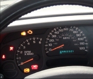
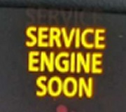
The issue happens randomly, both at a cold start and while driving down the road. One symptom common to the failure is that the in-dash lights (Check Guages, Service engine soon, Headlight symbol, Battery symbol. Etc.) That come on when you initially start the vehicle do not come on also, but if I mess around (rotating between) turning on the blinkers, turn signals, Hazards, headlights, even moving the tilt wheel up and down the lights will eventually come on (I hear the fuel pump cycle on) and it will fire right up.
It seems that the ignition switch lock tumblers are worn too and I am leaning towards replacing the whole switch. I swapped out my old worn key (Which I could pull out while in the run position) for my replacement one and that seemed to help a little (At least I couldn't pull it out while in the run position. :)), But did not fix the situation.

Some of the things I have done already; New Battery, new coil, new plug wires, new distributor (w/cap and rotor), new fuel pump, new spark plugs, new fuel and air filters, new alternator. Sheez, I'm going broke.

Any assistance would be greatly appreciated.

Thanks.
Friday, March 19th, 2010 AT 12:33 PM
1 Reply

Tiny
MERLIN2021
  • MECHANIC
  • 17,250 POSTS
I would remove the steering column plastic covers and check for any signs of a bare or pinched wire, if nothing found check the multifunction switch.(blinker).
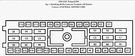
TESTING COLUMN SWITCHES Ignition & Turn/Hazard Switches 1. Turn ignition off. Disconnect Black 48-pin steering column harness-to-main harness connector under instrument panel. See wiring diagram in appropriate WIRING DIAGRAM article. 2. Connector terminals represented in wiring diagram (identified by a letter/number combination) match connector terminals of 48-pin connector illustrated. See Fig. 1 . 3. Connect one ohmmeter lead to power supply terminal of switch side of 48-pin connector. Connect other ohmmeter lead to appropriate terminal of 48-pin connector according to selected switch position. If continuity does not exist for selected switch position, problem is open in that circuit between 48-pin connector and switch, or faulty switch. Fig. 1: Identifying 48-Pin Connector Terminals (All Models) Courtesy of GENERAL MOTORS CORP. NOTE: For wiring diagrams and switch testing procedures on cruise control, lighting, wiper/washer and other components, see WIRING DIAGRAM article in ACCESSORIES & EQUIPMENT.
3/21/2010 ...


https://www.2carpros.com/forum/automotive_pictures/62217_1_66.jpg

Was this
answer
helpful?
Yes
No
+1
Sunday, March 21st, 2010 AT 10:09 AM

Please login or register to post a reply.

Sponsored links