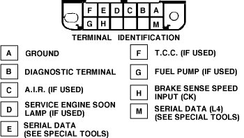
To extract a trouble from the computer for diagnostic purposes, the Assembly Line Communication Link (ALDL) connector is used.
Ground terminals A and B with the ignition "ON" and engine not running. The system will enter the diagnostic mode. In this mode, the computer will display a 12, three consecutive times, by flashing the "CHECK ENGINE", "SERVICE ENGINE SOON" or "MALFUNCTION INDICATOR LAMP" or light. A 12 consists of one flash, a short pause, then two flashes in rapid succession.
After 12 is displayed, any stored trouble s will be displayed by flashing the "CHECK ENGINE", "SERVICE ENGINE SOON" or "MALFUNCTION INDICATOR LAMP" light. All s are displayed 3 times each then a 12 will repeat. In the diagnostic mode, the computer will also energize all computer controlled relays and solenoids.

13 Open Oxygen Sensor Circuit
14 Coolant Sensor Circuit Shorted
15 Coolant Sensor Circuit Open
21 Throttle Position Sensor (Signal Voltage High)
22 Open Throttle Position Sensor Circuit
24 Vehicle Speed Sensor (VSS) Circuit
32 Exhaust Gas Recirculation System (Over 8500 GVW)
32 Exhaust Gas Recirculation System (Under 8500 GVW)
33 Manifold Absolute Pressure Sensor (MAP) Voltage High)
34 Manifold Absolute Pressure Sensor (MAP) Voltage Low)
35 Idle Air Control (IAC) System
42 Electronic Spark Timing (EST) Circuit
43 Electronic Spark Control (ESC) Circuit
44 Oxygen Sensor Circuit Lean Exhaust Indicated
45 Oxygen Sensor Circuit Rich Exhaust Indicated
51 Faulty Mem-Cal or PROM Problem
52 Fuel CALPAK Missing
53 Over Voltage Error
54 Fuel Pump Circuit (Low Voltage)
55 Faulty ECM
SPONSORED LINKS
Thursday, March 26th, 2009 AT 9:26 PM


