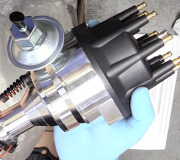
Here are a couple test to do on the Crank Shaft Position Sensor.
NOTE:
CIRCUIT PIN IDENTIFICATION
CIRCUIT TEST CKP2
Crankshaft Position Sensor NO. 2
NOTE:
CIRCUIT PIN IDENTIFICATION
2.5L has 2 crankshaft position sensors.
Circuit _________ Breakout Box Pin No. _________ PCM Pin_________ Wire Color
CKP1 ___________ 56 _________ 3E________ LightGreen/Orange
GND________ 49________3C _________Blk/Red
VPWR ______37 & 57_________1B________Red/Black
1) Check System Integrity Visually check all wiring, connectors and components for evidence of damage, shorting or looseness. If a fault is found, repair as necessary. If no fault is found, go to next step.
2) Check CKP1 Signal Turn ignition off. Install breakout box. Connect PCM to breakout box. Measure voltage at CKP1 test pin at breakout box while bumping starter. If voltage does not fluctuate between zero and 5 volts, go to next step. If voltage fluctuates between zero and 5 volts, CKP1 circuit is okay. If sent to this test by a specific code, replace PCM.
3) Check VPWR To Distributor Turn ignition off. Disconnect distributor connector. Turn ignition on. Measure voltage at distributor VPWR wire. If voltage is more than 10 volts, go to next step. If voltage is 10 volts or less, perform CIRCUIT TEST VPWR. If results of CIRCUIT TEST VPWR are okay, repair open in VPWR wire to distributor.
4) Check Distributor Ground Ensure ignition is off and distributor is disconnected. Measure resistance between distributor connector GND wire and ground. If resistance is less than 5 ohms, go to next step. If resistance is 5 ohms or more, repair open in distributor GND wire.
5) Check For Open CKP1 Wire Ensure ignition is off and distributor is disconnected. With breakout box installed, disconnect PCM connectors. Measure resistance of CKP1 wire between CKP1 test pin at breakout box and CKP1 terminal at distributor connector. See Fig. 5. If resistance is less than 5 ohms, go to next step. If resistance is 5 ohms or more, repair open CKP1 wire.
6) Check For Short In CKP1 Wire Ensure ignition is off and distributor is disconnected. With breakout box installed and PCM disconnected, measure resistance of CKP1 wire between ground and CKP1 test pin at breakout box. If resistance is more than 10,000 ohms, replace distributor. If resistance is 10,000 ohms or less, repair short to ground in CKP1 wire.
Enter this test only when Code 02 is displayed during self-test procedures (KOEO or KOER) or when directed here from another circuit test. This test is intended to diagnose CKP2 circuit only.
1) Check System Integrity Visually check all wiring, connectors and components for evidence of damage, shorting or looseness. If a fault is found, repair as necessary. If no fault is found, go to next step.
3) Check VPWR To Distributor Turn ignition off. Disconnect distributor connector. Turn ignition on. Measure voltage at distributor VPWR wire. If voltage is more than 10 volts, go to next step. If voltage is 10 volts or less, perform CIRCUIT TEST VPWR. If results of CIRCUIT TEST VPWR are okay, repair open in VPWR wire to distributor.
I will email the rest to you in an xps file.
.
Thursday, April 15th, 2010 AT 8:17 PM


