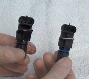
Both TACH wire and BATT wire have power when the key is in the run and start position but still no spark out of the coil. I found the ECC module under the driver seat, could that ECC module be bad?
RUN CIRCUIT CHECK 1. Disconnect ignition module 3-wire connector, and install ignition diagnostic test adapter (T79P-12127-A or equivalent) as shown in Fig. 5. Disconnect ignition coil wire from distributor, and connect spark tester to coil wire and engine ground. Fig. 5: Ignition Diagnostic Test Adapter and Spark Tester Hook-Up for Run Circuits Check Spark should occur at tester, when lead is touched to battery positive terminal. 2. Turn ignition switch to "RUN" position, and touch diagnostic adapter lead to positive battery terminal. Sparks should occur at tester gap each time lead touches battery terminal. Turn ignition switch "OFF", remove spark tester, and remove ignition diagnostic test adapter. Reconnect all wires. 3. If sparks occurred at tester gap, proceed to "Start Circuits Check". If no sparks occurred attester gap, proceed to "Ignition Coil Primary Circuit Switching Check". START CIRCUIT CHECK 1. Disconnect ignition coil wire from distributor cap, and attach spark tester to wire and engine ground. Crank engine, using ignition switch. Disconnect spark tester, and reconnect coil wire to distributor. 2. If spark occurred at tester gap, inspect distributor cap, adapter and rotor for cracks, carbon tracking, rotor alignment or lack of silicone compound. If sparks did not occur at tester gap, proceed to "Voltage Supply Circuits Check". IGNITION COIL PRIMARY CIRCUIT SWITCHING CHECK 1. Disconnect ignition module 3-wire connector and install diagnostic adapter (T79P-12127-A or equivalent). Connect a test light between "TACH" terminal of ignition coil and an engine ground. With ignition switch in "RUN" position, touch diagnostic adapter test lead to positive battery terminal. 2. Test light should flash each time test lead is either connected to or removed from battery terminal. Turn ignition switch "OFF", remove diagnostic adapter, and reconnect ignition module wires. 3. If test light flashes, proceed to "Ignition Coil Secondary Resistance Check". If test light does not flash or is dim, proceed to "Voltage Supply Circuits Check". IGNITION COIL SECONDARY RESISTANCE CHECK 1. Disconnect ignition coil connector and secondary wire from ignition coil. Connect ohmmeter leads to "TACH" and secondary terminals of ignition coil. Measure resistance, remove ohmmeter leads, and reconnect coil wires. 2. If resistance was 7700-10,500 ohms, coil is OK. Measure resistance of ignition coil-to- distributor wire. 3. If wire resistance is greater than 5000 ohms per inch, replace ignition coil wire and proceed to "Ignition Coil Primary Resistance Check". If coil resistance is less than 7000 ohms or greater than 10,500 ohms, replace ignition coil. VOLTAGE SUPPLY CIRCUITS CHECK 1. If starter relay has an "I" terminal, disconnect cable from starter relay to starter motor. If starter relay does not have an "I" terminal, disconnect wire to "S" terminal of starter relay. Carefully insert small straight pins in Red and White ignition module wires. See Fig. 6.
CAUTION: Do not allow straight pins to contact an electrical ground.2. Measure battery voltage at battery, then measure voltage in each of the following situations at points indicated: � � � With ignition switch in "RUN" position, connect voltmeter negative lead to an engine ground and positive lead to straight pin in Red wire. � � � With ignition switch in "START" position, connect voltmeter negative lead to an engine ground and positive lead to straight pin in White wire. � � � With ignition switch in "START" position, connect voltmeter negative lead to an engine ground and positive lead to ignition coil "BATT" terminal. 3. Turn ignition switch "OFF", remove voltmeter and straight pins, and reconnect starter relay cables. If voltage was at least 90 percent of battery voltage, proceed to "Ignition Coil Voltage Supply Check". 4. If voltage was less than 90 percent of battery voltage, inspect wiring harness/connectors or damaged ignition switch. IGNITION COIL VOLTAGE SUPPLY CHECK 1. Attach negative lead of voltmeter to engine ground, and positive lead of voltmeter to "BATT" terminal of ignition coil. Turn ignition switch to "RUN" position and measure voltage. Turn ignition switch "OFF". 2. If voltage was 6-8 volts, proceed to "Module-to-Coil Wire Resistance Check". If voltage was less than 6 volts or greater than 8 volts, proceed to "Ignition Coil Primary Resistance Check". MODULE-TO-COIL WIRE RESISTANCE CHECK 1. Disconnect ignition coil connector from ignition coil, and disconnect ignition module 3-wire connector. Connect ohmmeter leads to engine ground and "TACH" terminal of ignition coil connector. 2. Measure resistance. Remove ohmmeter leads, reconnect ignition module and coil connectors. 3. If resistance was greater than 1 ohm, replace ignition module. If resistance was 1 ohm or less, inspect wiring harness between ignition module and ignition coil. IGNITION COIL PRIMARY RESISTANCE CHECK 1. Disconnect ignition coil connector. Connect ohmmeter leads to "BATT" and "TACH" terminals of ignition coil. Measure resistance, remove ohmmeter leads, and reconnect ignition coil connector. 2. If resistance was 0.8-1.6 ohms, proceed to "Module-to-Coil Wire Voltage Check". If resistance was less than 0.8 ohm or greater than 1.6 ohms replace ignition coil. MODULE-TO-COIL WIRE VOLTAGE CHECK 1. Carefully insert a small straight pin in Green ignition module wire. Turn ignition switch to "RUN" position. 2. Attach negative lead of voltmeter to engine ground, and positive lead to straight pin in Green wire. Observe reading. Move positive lead to "TACH" terminal of ignition coil, observereading. Turn ignition switch "OFF", remove pin from wire. 3. If the difference in voltage readings was less than 0.5 volt, proceed to "Primary Circuit Continuity Check". If difference in voltage readings was greater than 0.5 volt, inspect wiring harness between ignition module and ignition coil. PRIMARY CIRCUIT CONTINUITY CHECK 1. Carefully insert a small straight pin in Green ignition module wire. Connect negative voltmeter lead to engine ground and positive voltmeter lead to pin in Green wire. 2. Turn ignition switch to "RUN" position, and measure voltage. Turn ignition switch "OFF", remove voltmeter and straight pin. 3. If voltage was greater than 1.5 volts, proceed to "Ground Circuit Continuity Check". If voltage was 1.5 volts or less, proceed to "Ballast Resistor Check". BALLAST RESISTOR CHECK 1. Disconnect ignition module 2-wire connector. Disconnect ignition coil connector from ignition coil. 2. Connect ohmmeter leads to "BATT" terminal of ignition coil connector and to wiring harness terminal that mates with Red module wire. Measure resistance. Reconnect ignition coil and ignition module connectors. 3. If resistance was 0.8-1.6 ohms, replace ignition module. If resistance was less than 0.8 ohm or greater than 1.6 ohms, replace ballast resistor. GROUND CIRCUIT CONTINUITY CHECK 1. Carefully insert a small straight pin in ignition module Black wire. Attach negative voltmeter lead to ground. Attach positive voltmeter lead to straight pin. 2. Turn ignition switch to "RUN" position, measure voltage. Turn ignition switch "OFF", remove straight pin. 3. If voltage was more than 0.5 volt, proceed to "Wiring Harness Ground Circuit Check". If voltage was less than 0.5 volt, replace ignition module. WIRING HARNESS GROUND CIRCUIT CHECK 1. Disconnect ignition module 3-wire connector. Connect ohmmeter leads to engine ground and terminal in wiring harness connector that mates with Black wire of ignition module. 2. Measure resistance. Reconnect ignition module 3-wire connector. 3. If resistance was less than 1 ohm; inspect Black wire, ignition module connector and wiring harness. If resistance was greater than 1 ohm, inspect wiring harness/connectors between ignition module and ground. SPARK PLUG WIRE CHECK 1. Disconnect spark plug end of suspected wire or wires. Remove distributor cap. Measureresistance of spark plug wires by touching ohmmeter probes to each end of wire. Measure from inside distributor cap. If resistance is less than 5000 ohms per inch, wire is OK. 2. If resistance is more than 5000 ohms per inch, remove wire from cap and measure resistance of wire only. 3. If resistance is less than 5000 ohms per inch, wire is OK. Check distributor cap and spark plug terminal for corrosion. If resistance is more than 5000 ohms, replace spark plug wire. All this was in the PDF I sent. See testing Tach and Ballast resistor.
Saturday, March 21st, 2009 AT 8:28 AM


