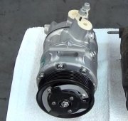
CLUTCH ASSEMBLY
Removal
Discharge A/C system, using approved refrigerant recovery/recycling equipment. Remove compressor. Using a spanner wrench or clutch holder, remove clutch plate bolt. Discard bolt. Thread an 8-mm bolt into clutch plate, and remove clutch plate and shims.
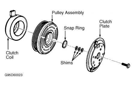
Remove pulley outside snap ring. Remove pulley assembly. See Fig. 1 . Disconnect clutch coil lead. Install Shaft Protector (T89P-19623-FH) over compressor shaft. Install 2-jaw puller on compressor. Carefully tighten puller to remove clutch coil from compressor. DO NOT use air-powered tools when removing clutch coil.
Installation
Ensure clutch coil mounting surface is clean. Install clutch coil. Ensure electrical connection is correctly positioned. Position Coil Replacer (T91L-19623-CH) onto coil and Coil Pressing Adapter (T89P-19623-EH) onto coil replacer.
Install 2-jaw puller on compressor and coil replacer. Engage jaws on puller with compressor front mounts. Carefully tighten puller until clutch coil bottoms completely against compressor. DO NOT use air-powered tools when installing clutch coil.
Carefully install pulley assembly onto compressor, ensuring that it is properly aligned. Install pulley assembly snap ring with beveled side out. Install shim(s) and clutch plate. Install NEW clutch plate bolt, and tighten it to 98-123 INCH lbs. (11-14 N.m).
Using a feeler gauge, measure air gap between clutch plate and pulley assembly mating surfaces in 3 places. Air gap should be 0.014-0.033" (0.36-0.84 mm). If air gap is not as specified, add or remove shims as necessary.
Fig. 1: Exploded View Of Compressor Clutch Assembly (Typical)
Courtesy of FORD MOTOR CO.

Monday, April 19th, 2021 AT 3:05 PM


