Removal (Lower)
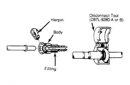
Release fuel pressure. See FUEL PRESSURE RELEASE . Disconnect negative battery cable. Using Disconnect Tool (D87L-9280-A or B), disconnect fuel supply and return line. See Fig. 2 .

If hairpin-type retainer is used, remove hairpin by bending tab downward so it will clear body. Using your hands, spread clip legs .125" (3 mm) and push legs into fitting. Pull hairpin clip from fitting. See Fig. 2 .
Remove upper intake manifold as previously described. Remove distributor cap and plug wires as an assembly. Position engine on No. 1 cylinder TDC of compression stroke. Align TDC marks on crankshaft damper with front cover index plate. Mark and remove distributor assembly.
Mark and disconnect electrical connectors and vacuum hoses from lower manifold. Remove fuel injector wiring harness. Note oxygen sensor wire-to-stud location for installation reference, and remove ground wire. Remove upper radiator hose, by-pass hose and heater outlet hose.
Remove air cleaner bracket. Remove ignition coil bracket and set aside. Remove lower intake manifold bolts evenly. Remove lower intake manifold and gaskets.
Installation
Clean gasket mating surfaces. Apply a 1/16" (1.6 mm) bead of silicone rubber sealer on full width of each intake manifold seal (4 places). Install new lower intake manifold gaskets on cylinder block and heads.
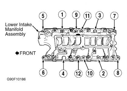
Ensure gaskets are interlocked with end rubber gaskets. Install 2 guide pins in opposite corners. Install lower intake manifold and tighten bolts finger tight. Tighten bolts evenly in sequence to specification. See Fig. 3 . See TORQUE SPECIFICATIONS table at end of article. To complete installation, reverse removal procedure. Fill and bleed air from cooling system. See, in this article, COOLING SYSTEM BLEEDING .
Fig. 3: Lower Intake Manifold Tightening Sequence

SPONSORED LINKS
Saturday, February 7th, 2009 AT 9:23 PM


